This page centralizes documentation relating to the module loading, integration, and quality control/assurance testing of the Inner System, part of ATLAS' Inner Tracker Pixels Phase II upgrade project.
Calendar of the personnel on site
| Noprint | ||||||
|---|---|---|---|---|---|---|
Table of Contents
|
Quick access resources for module loading & integration
- Module mechanical drawings (AT2-IP-EP-0009 v4)Dummy Heaters information including drawings, dimensions, soldering procedures, and testing
- Quad module properties
- 3D-printed dummy ring properties
- SE4445 cartridges at SLAC: Glue in freezer log
- Access the Electronic Logbook & its documentation
- On-site access during COVID-19
Loading and integration prototypes
Thermomechanical prototypes: Coupled ring & L0 stave
p19-0
- Dummy Heaters information including drawings, dimensions, soldering procedures, and testing
Ring loading [Tubes Up] [Tubes Down] [gDoc with loading notes for each side]
Stave loading [p19-0 stave anatomy]
Electrical prototypes: Coupled ring, 2x L1 stave, L0 stave
p19-1
Ring loading [gDoc]
Links for the 4 AUW presentations, ATLAS Digest link
Integration prototype
p19-2
Module loading pages
Building 33: Module loading equipment
Consumable components for mixing and dispensing SE4445
A list of consumables required for mixing SE4445, storing it in syringes, and dispensing it with the Janome robot.
The linked page includes the information required to place orders for each item.
Glue dispensing equipment
Page describing the air dispenser, PC, and Janome robot for glue dispensing. The page labels the equipment. The operations instructions are obsolete. Please follow the latest instructions here.
- In addition, we now have an edge finder we can mount on the robot.
Quad & triplet pick up plates
- CMM measurements from October 23 & 29, 2020; February 25, 2021
- Pickup Plates w- grooves.pdf
- REF-000112056 RD53a Ring_Triplet top view only.pdf
- some dimensions from PF-256-102-70.pdf
- view of PF-256-102-30 PICK UP PLATE SGL-TPL with 20mm slides.pdf
- view of PF-256-102-30 PICK UP PLATE SGL-TPL with 22mm slides.pdf
Equipment manuals
- Nordson EFD Ultimus V dispenser [PDF] [Confluence page]
- Checking the temperature of a syringe with the IR camera [Confluence]
- Janome Points software [Confluence]
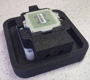
- ITk pixel module QC cooling unit [Confluence]
Datasheets
Further documentation and resources
Datasets
Related presentations
- LBL-loaned Keyence glue mixer (returned to LBL, replace with SLAC mixer when ordered)
Datasheets
Module mounting glue options
Building 33: Operating procedures
Mixing SE4445 cartridges for storage
- This page describes how to set up and mix SE4445 into smaller smaller syringes for later use in the B33 cleanroom complex gowning area.
Building 33 - Glue freezer monitoring setup
Page describing the setup of the LabJack 7 + thermocouples, as well as monitoring software, PC setup, network setup.
Dispensing SE4445
- Step-by-step procedure for using the Nordson dispenser and robot in B33 to deposit SE4445 in a star pattern.
- Advanced programming concepts for the Janome Points software
- We can only predict so many eventualities: This page describes how to create your own custom Janome Points program file. It breaks down some key concepts (like Janome jargon "Point Job," "PTP," and "palette") as well as how to set up the Janome Points programme.
Running the CMM
- Describes how to operate the CMM in the small clean room in B33
Rework procedure
- Using fishing line and ethanol, we can remove heaters from staves. [Confluence]
Analyzing glue dispensing performance
Coverage
Glue layer thickness
Extract glue layer area from images collected of samples on a clean, solid, high-contrast background.
Please note that a ruler or other clearly known dimension must be in the image frame to provide a pixel-real world coordinates calibration source.
Charlie created a MATLAB script for measuring coverage in images of dispensed samples collected on a clean white background.
Alternatively, we can extract these areas with image processing tools like ImageJ.
Hannah and Rachel prepared Python-based scripts to analyze csv files containing height gauge measurement results. The (messy) scripts are available on GitLab:
Further documentation and resources
Datasets | Tables of wet and dry dispensing datasets collected after October 2020 |
|---|---|
Related presentations | Contains copies of lab notes and documents in addition to links for relevant presentations between August 2018 and February 2020 |
Module mounting glue options |
|
Obsolete loading tooling
- 19-0 style
Temporary quad & triplet pick up plates for thermomechanical prototype's loading tooling
- CMM measurements from October 23 & 29, 2020; February 25, 2021
- Pickup Plates w- grooves.pdf
- REF-000112056 RD53a Ring_Triplet top view only.pdf
- some dimensions from PF-256-102-70.pdf
- view of PF-256-102-30 PICK UP PLATE SGL-TPL with 20mm slides.pdf
- view of PF-256-102-30 PICK UP PLATE SGL-TPL with 22mm slides.pdf
- Lexar loading bridge
- Stave loading tooling (baseplate + loading bridge + pick up plate)
- Ring loading tooling (di-quad bridge & pick up plate, triplet bridge & pick up plate, baseplate)
Integration Pages
|
|
|
|
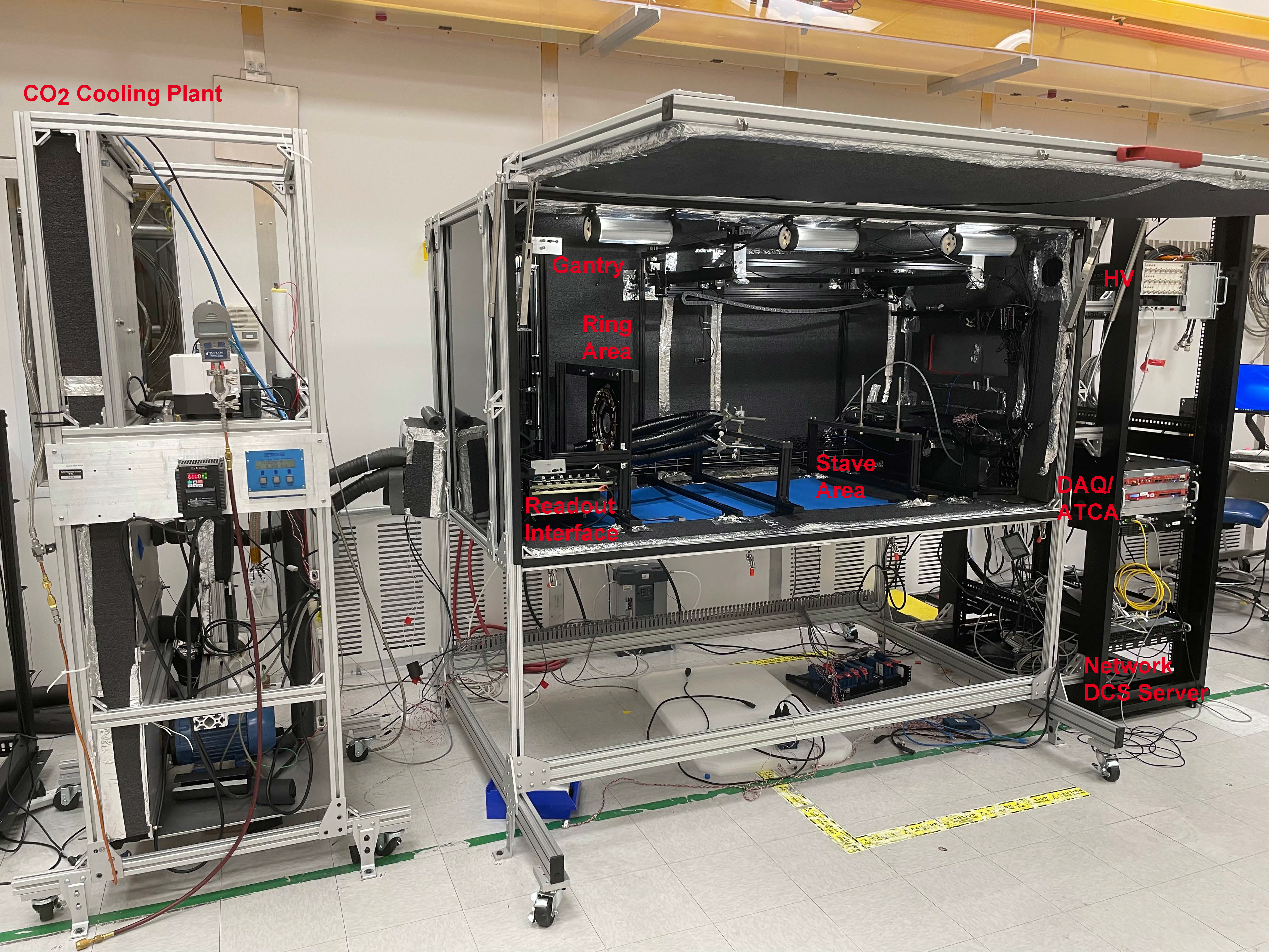
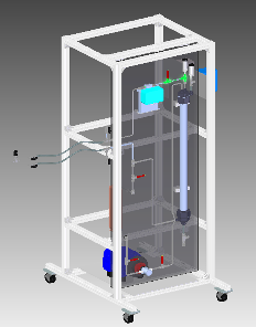
Q/C Box Electrical/Readout SetupElectrical and readout setup description, connectivity and collection of component design links. | B33-CO2 Plant Approved ProcedureCO2-plant equipment information, approved procedures and hazard | B33 |
Integration Pages
- Operating the QC Test BoxProcedures for operating the CO2 Plant and test box equipment |
Thermal Test pages
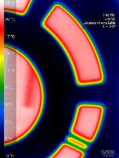
Thermal TestDescription and details on thermal test procedures. |
Discussion on Stavelet strategy [Confluence, 2019-08-21]
2019 requirements for the design and instrumentation in the SLAC test box [Confluence]
Readout and Q/C setups
 |
|
|
|
|
|---|---|---|---|---|
ITk pixel DAQ readout infrastructure and network at SLAC. This page requires ATLAS-confluence-editor permission |
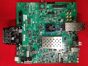
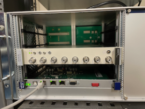
FELIX readout
FELIX readout system documentations, direct FELIX setups, and test configurations.
![]()
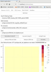
YARR Readout
YARR test bench documentations.

RCE ReadoutRCE test bench documentation for SLAC ITk local setups. More general RCE readout documentations |
on CERN Twiki RCEDevelopmentLab | YARR ReadoutYARR test bench documentations. | Felix readout documentation for the Felix712 | Direct FELIX readoutFELIX readout system documentations, direct FELIX setups, and test configurations. |
|
|
|
|
|---|---|---|---|
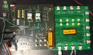
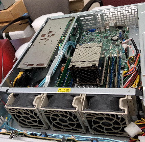
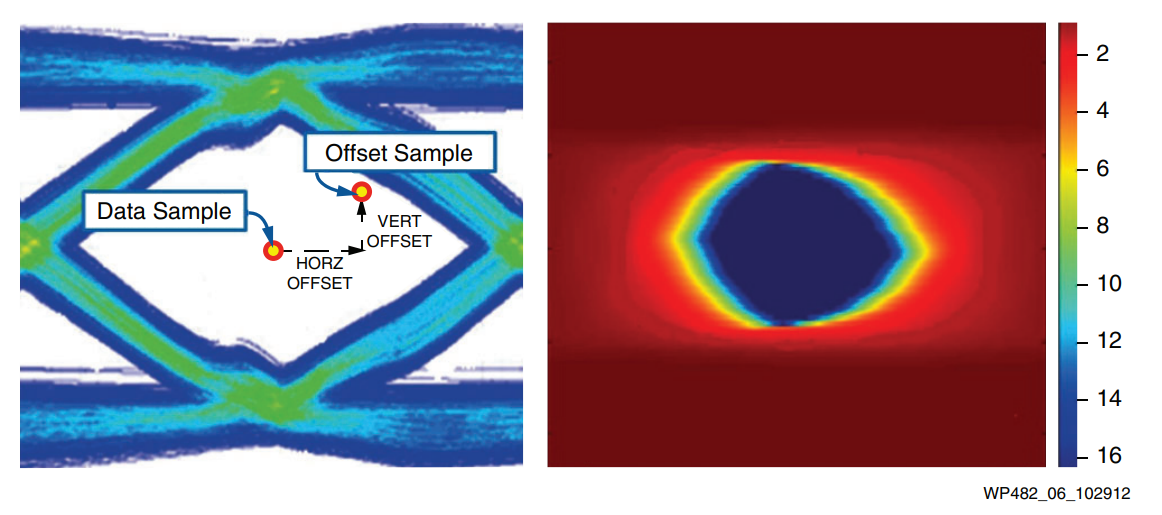
Electrical-Optical data transmission conversion system | ATCA system to support larger number of Rd53 readout | General DAQ operation GUI interface and instructions common to all DAQ platforms | The xilinx IBERT test is analternative solution for the traditional chipscope eye-diagra |
|
|
|
| |
|---|---|---|---|---|
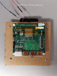
Module Q/C & Reception Test PortalModule general info. Test spec and infrastructure. Module inventory. | Cooling Unit for Module QCInformation on cooling unit for module QC |
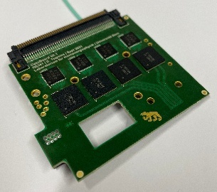
a readout chain includes ITkPixV1 chip, GBCRv2, VLDB+, and DAQ | DCS control/monitoringInformation on infrastructure and instructions for LV/HV PSU control and monitoring | DCS InterlockInterlock setup for Lab and B33 integration |
Some useful links:
1) simple User Guide for the ATCA Shelf Manager
2) ITk construction Google Drive
3) Module Reception microscope image collection on Google Drive
Manuals:
1) RD53a user manual
2) RD53B user manual
3) GBCR design and testing
4) DAQ with FELIX+Optoboard+YARR by Ismet (links to documentation within!)