General FELIX Documentations
- FELIX user manual
- RD53A readout with FELIX and YARR system setup (ATL-COM-DAQ-2019-160))
- FLX-712 manual
- Interface board schematic
Related DAQ/Electronics Documentations
- GBT and Versatile Link: VLDB eSpace
- lpGBT and Versatile Link+: lpGBT, VLDB+
- VLDB schematic
- RD53a SCC schematic
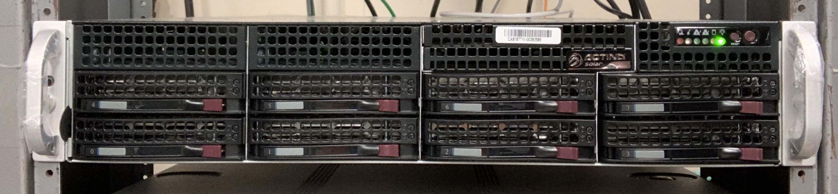
B33 Integration FELIX Setup
B84 FELIX Test Setup
|
 |
|---|---|
| |
|
FELIX Configuration Process
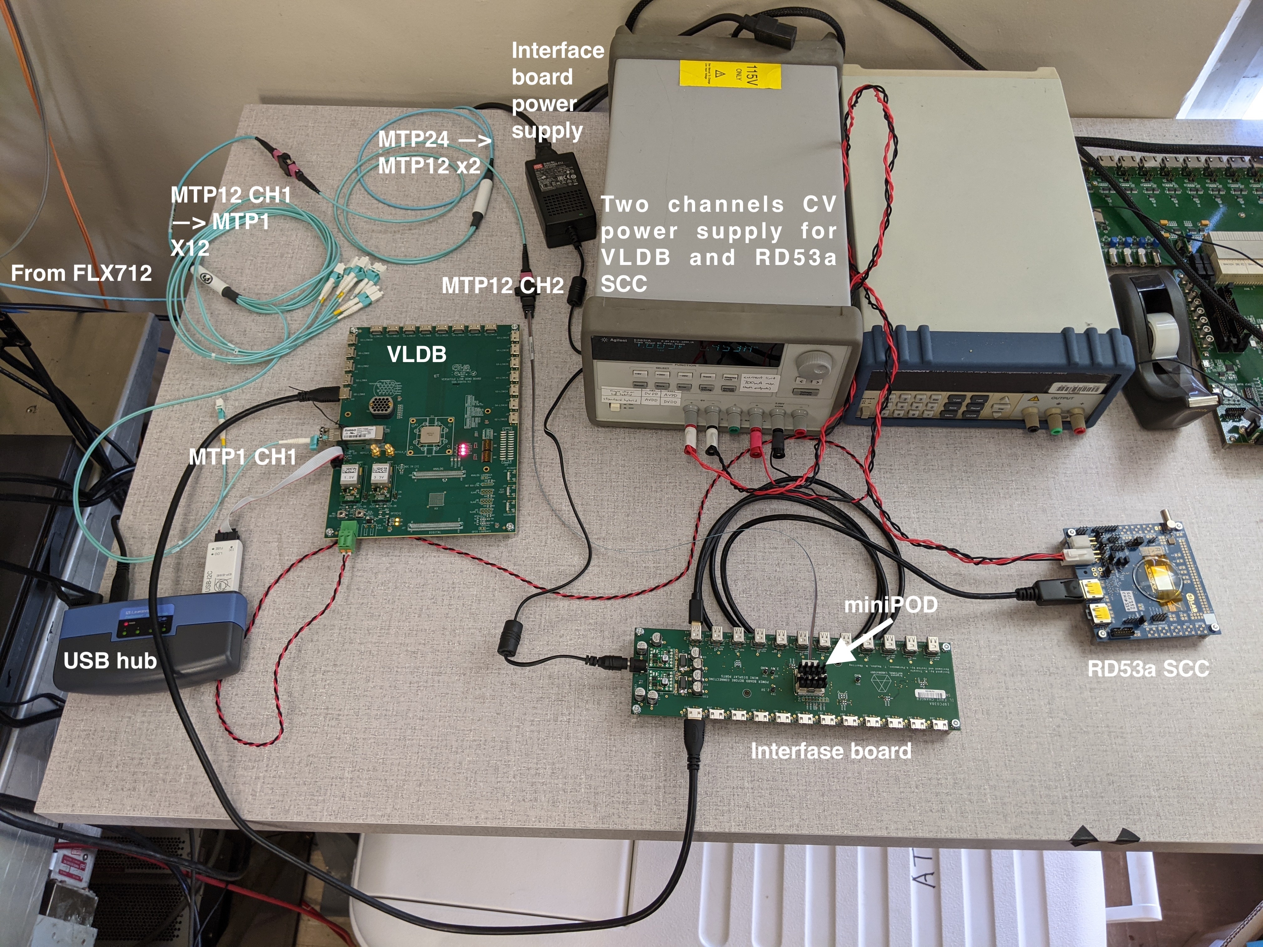
- Assemble the test stand according to figures from the "B84 FELIX Test Setup" section:
- Plug any of MTP12_CH1_STX cables where X = 1, 2, 3 or 4 (labeled as "1", "2", "3" or "4") into the VLDB's RX. Setup at SLAC uses X = 1.
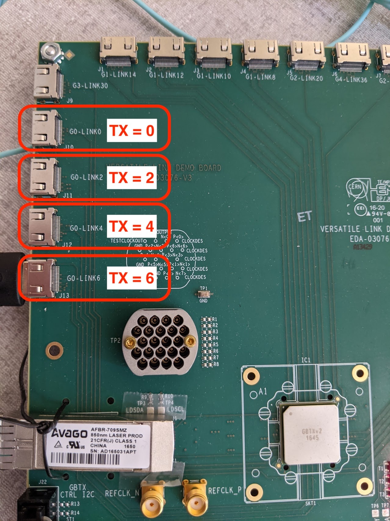
- Plug mini-HDMI in G0-LinkX on VLDB, where X = 0, 2, 4 or 6. The X value will further be used as "TX" parameter in YARR configs.
- Use J77 for mini-HDMI and J93 for mini-DP on the interface board (more details in the board's schematics why). Mini-HDMI and mini-DP ports standing one against another are coupled.
- Configure VLDB (GUI is needed for java):
- Supply 5VCC with 1A limit in current to VLDB. With 5V input voltage a VLDB may consume as low as 300mA. Once the VLDB and FELIX configuration processes are done, the board consumes about 450mA.
- Use the .jar programmer file and the txt config file.
- In the command line run:
$ java -jar programmerv2.20180725.jar
(Java GUI will appear) - Click "import i..." in the top left corner and select the txt config file.
- Click "Write GBTX". After the process is done, GUI should look like the attached screenshot

- Update/install the most recent Felix firmware (assuming Vivado Lab is installed, and one has access to GUI):
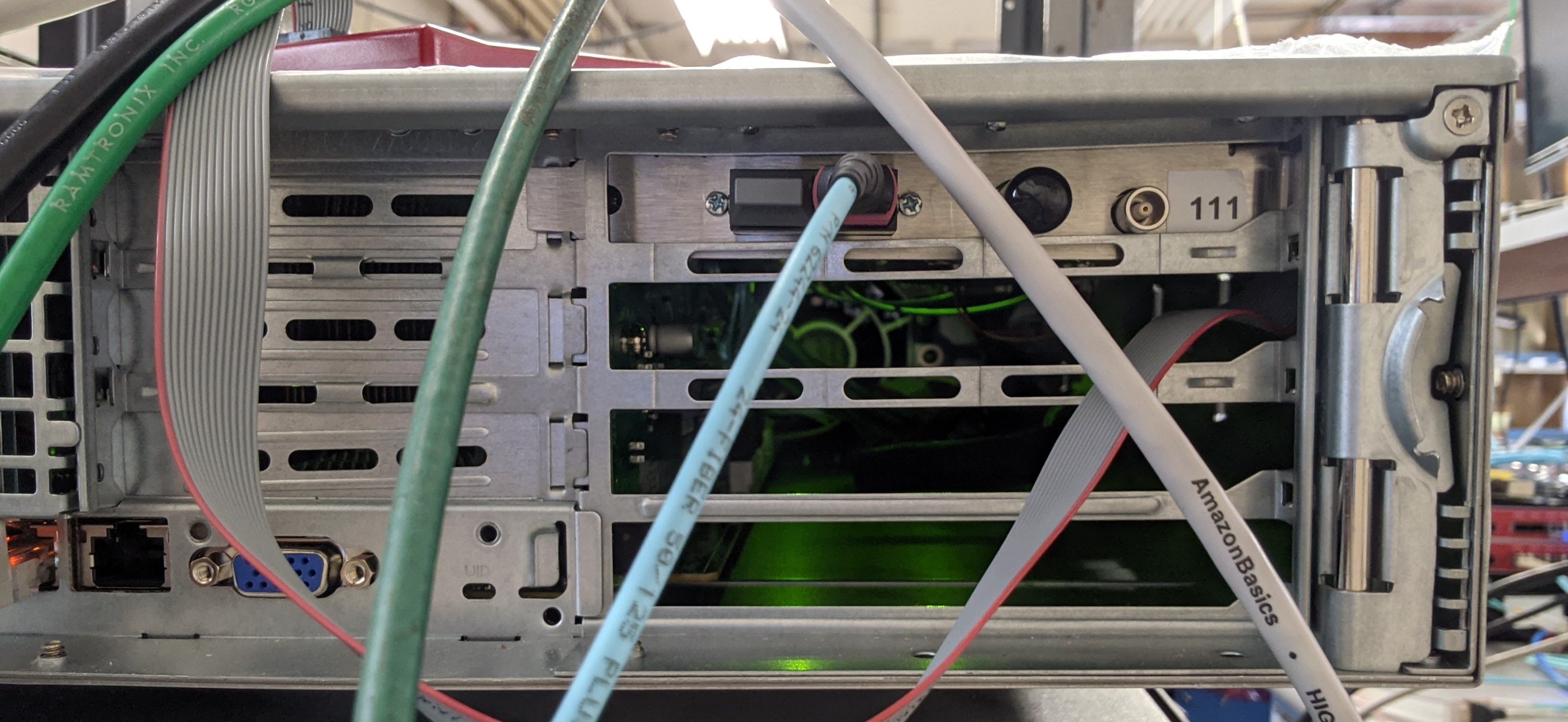
Plug in a JTAG-USB cable in a correct port on the FLX-712 board.

SLAC FLX-712 Board

ANL FLX-712 Diagram

Xilinx Dongle:
No LED light: PC doesn't see the dongle. Check drivers.
Yellow LED: No target. Check JTAG connections.
Green LED: Good! Can Proceed.
- Get Felix firmware from CERN Box.
- In Vivado Lab detect the target, use the .bit file to configure.
- Reboot the PC.
- Unplug the MTP12-CH1-TXA fiber from the VLDB and make sure you observe red light coming from the fiber. Plug in the fiber back to the VLDB's RX.
- If there is no GUI and/or Vivado on the Felix server, one may use an external PC to configure the FLX-712 board: keep the board in the server, plug the Xilinx USB dongle into the external PC and run Vivado from there.
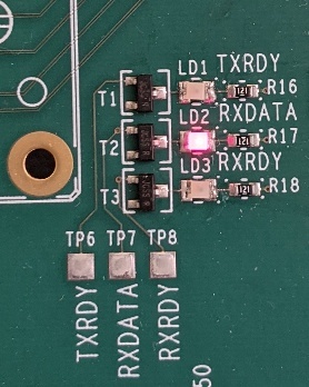
- Now you should see the RXDATA LED lighting with dim red color.
- Set up FELIX.
Depends on the number of FLX cards and their actual locations (PCIe ports) in your PC, option -c / -d in the following commands may vary. In the simplest case of one FLX card follow use same values as below.- Run from /home/USER/FELIX/felix-*/x86_64-centos7-gcc8-opt/
$ source "path_to_felix"/source.sh - Run from
$ flx-init -c0
Run the init command only once. If you run it twice or more in one session, you need to reboot the computer.
Get information about your FELIX:
$ flx-info -c0
May omit the info command, but it is useful to crocs-check that everything is ok. - Check polarity of the channels:
$ flx-config -d0 list | grep POLARITY
$ flx-config -d1 list | grep POLARITY
TX polarity must be inverted, otherwise readout is not possible.
If you observe "GBT-TXPOLARITY 0x000000000000", run:
$ flx-config -d1 set GBT-TXPOLARITY=0xffffffffffffffff
$ flx-config -d1 set GBT-TXPOLARITY=0xffffffffffffffff - If everything was done properly, the other two LEDs - TXRDY and RXRDY - should light up:

- Run from /home/USER/FELIX/felix-*/x86_64-centos7-gcc8-opt/
- Configure E-links in elinkconfig.
elinckconfig tool is described in the Felix manual - Section 6.1.
The procedure must be done after each system reboot.
TL;DR:- $ source "path_to_felix"/source.sh (if not done yet)
- $ elinkconfig
elinkconfig GUI appears:

Initial state of the elinkconfig

Target state of the elinkconfig
- Click "FULLmode" in the top panel. The left panel will collapse into just one box named "Enable FULLMODE": check the small box, and the entire block will turn orange.
- Check "TTC-to_Host (63b)" box in the top panel.
- Uncheck all the Epaths in the right panel: select "Egroup 0" on the bottom right, click "Disable" on the bottom right, click "Relp 2 All" on the bottom right; uncheck "EC (3f)" by hand.
- Click "2-bit" drop down button under the Egroup 0 and select "4-bit".
- Check Egroup0-EpathX according to your setup (G0-LinkX mini-HMDI ports on the VLDB).
Click "TH_FanOut..." on the top menu. New window will appear, click "None" and "OK". Repeat same for "FH_FanOut".

"ToHost FanOut" Initial state (same for "FromHost")

"ToHost FanOut" Target state (same for "FromHost")
- Click "Repl 2 All" on the top panel.
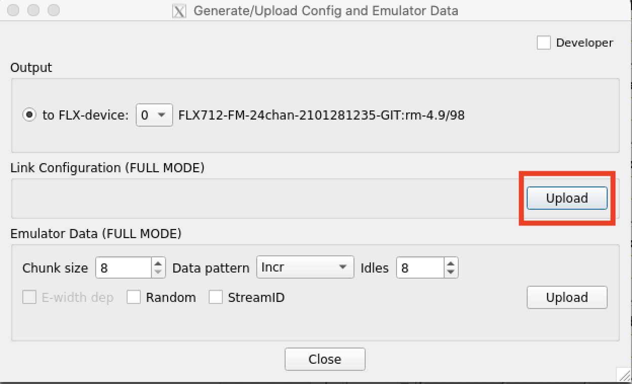
- Save the configuration: click "Generate/Update" on the top panels. new window will appear, click the top "Upload" button and "Close".
- Click "FLX-device" breakdown menu on the top panel, select 1 instead of 0. Repeat same procedure for the device 1. (NOTE: number of devices and their actual address depend on the number of FLX-712 cards used in a server. In case of one card use only 0 and 1.)
- Check some FELIX registers:
- flx-config -d0 list | grep GBT_GENERAL_CTRL
If returns other than 0x0000000000000004, run:
flx-config -d0 set GBT_GENERAL_CTRL=0x4 - flx-config -d0 list | grep GBT_ALIGNMENT_DONE
returns 0x0..f..0 when an RD53a SCC is connected (one "f" for each SCC). - flx-config -d0 list | grep GBT_RXCDR_LOCK
returns 0x0..f..0 when an RD53a SCC is connected (one "f" for each SCC).
- flx-config -d0 list | grep GBT_GENERAL_CTRL
Running YARR Scans with FELIX
Build YARR.
Get the correct version of YARR SW - to be updated.
There are typos in both YARR gitlab readme and Felix documentation. The actual cmake3 command is:
$ cmake3 -DYARR_CONTROLLERS_TO_BUILD="Spec;Emu;NetioHW" ..
Create a config file for the SCC itself.
First, copy the default to have your own config file:
$ cp configs/defaults/default_rd53a.json configs/rd53a_0.json
Set 1280 Mbps speed in the config file:
"CdrSelSerClk": 0,
Prepare a connectivity config file.
First, copy the default example to modify your own config file (from YARR/):
$ cp configs/connectivity/example_rd53a_setup.json configs/connectivity/my_config.json
Set path to your config file for RD53a under "config".
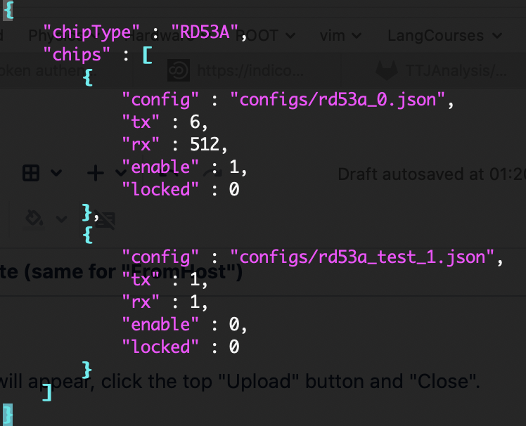
Then, one need to know RX and TX for YARR config file: YARR/configs/connectivity/example_rd53a_setup.json
A regular config file is shown in left figure below. TX is known from the test stand assembly.
|
FELIX TX Values Explained |
|---|
Open two terminal windows. Source the Felix setup.src in both windows. To get the RX file one need to run a simple injection from one terminal window and monitor the process in parallel.
To run the simple injection from in the first terminal follow next steps:
- Get "CalInjections.sh" and "commands.tgz" from cernbox.
- Untar the commands.tgz
- In the CalInjections.sh set correct parameters:
- -d : logical device, in the simples setup with one FLX card is 0.
- -G : physical link, is the X value form GX-LinkY name of the mini-HDMI port used on the VLDB (usually 0).
- -g : egroup, refer to the elinkconfig settings, usually 0.
- -p : path, same as TX. Can be taken from the TX map on the photo above or from elinkconfig - values are the same.
- In total, for a test stand same as described in the manual the parameters should be "-d 0 -G 0 -g 0 -p 6".
- Run in the terminal:
$ ./CalInjections.sh
In the second terminal:
- Run from /home/USER/FELIX/felix-*/x86_64-centos7-gcc8-opt/ :
$ fdaq -d0 -t30 -X test1.dat
where -t sets time to run the scan in seconds, -X sets an output file. - While the scanning is up, repeat CalInjection in the first window.
- Once the scanning is done, analyze the data file:
$ fcheck test1-*.dat (note the test1 is the same as what comes in-X of ./fdaq command).
Check the first value (G) below G-g-p. RX = G*64. In the example below RX = 8*64 = 512.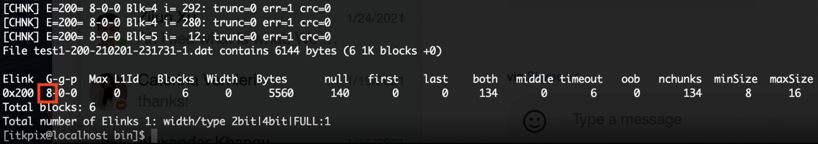
Run scans with RD53a SCC.
First, reboot the PC. Reboot is required after each time a user run CalInjection.sh . Repeat the routine Felix setup procedure described in sections "FELX Configuration Process - 4. Set up FELIX" and "FELX Configuration Process - 5. Configure E-links in elinkconfig".
Run FELIX core in the terminal window:
$ felixcore -t 1 --data-interface lo
where -t 1 specifies time (1h), and lo (LO) is the default name of the loopback address socket for CentOS7 machines.
Wait until the FELIX core command will return "FelixCore Up and Running..." in the terminal window (last line).
Open the second terminal window, navigate to the YARR SW directory, and run a (digital) scan from there:
$ bin/scanConsole -r configs/controller/felix.json -c configs/connectivity/example_rd53a_setup.json -s configs/scans/rd53a/std_digitalscan.json -p