This is a step-by-step procedure to use the Nordson Robot in B33 to deposit SE4445 in the star pattern. This page supersedes the content at Building 33 - Setting up for gluing in the lab.
Step-by-step guide
Turn dry-air valve counterclockwise half-turn.
There should be a hissing noise from the air flow.This dry air is used to control EFD and height gauge.
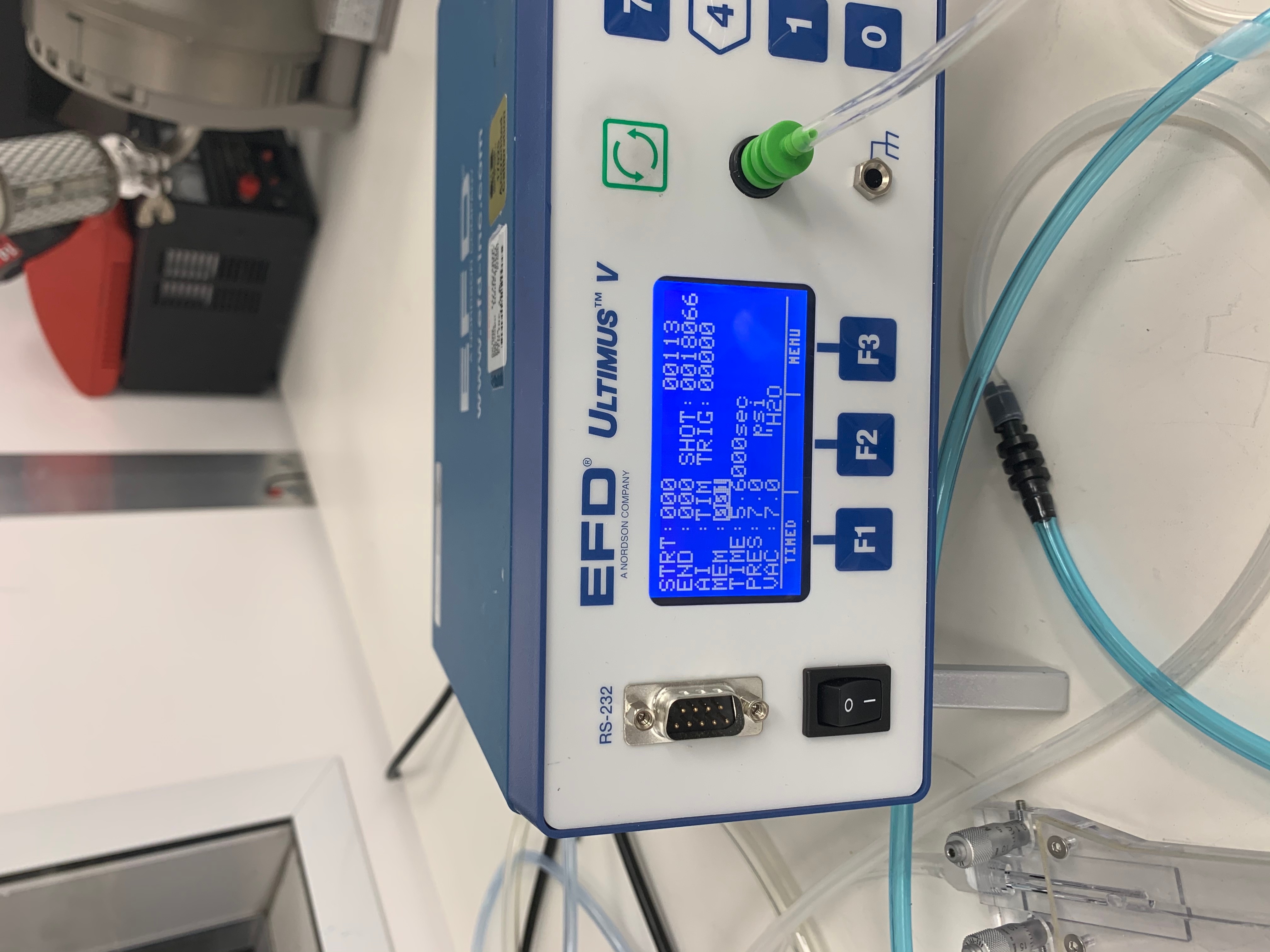
Turn EFD on
The screen will display a default menu.
The settings for SE4445 are preset 001 and make sure it is set on "steady".To change the settings refer to Building 33 - Setting up for gluing in the lab for instructions.
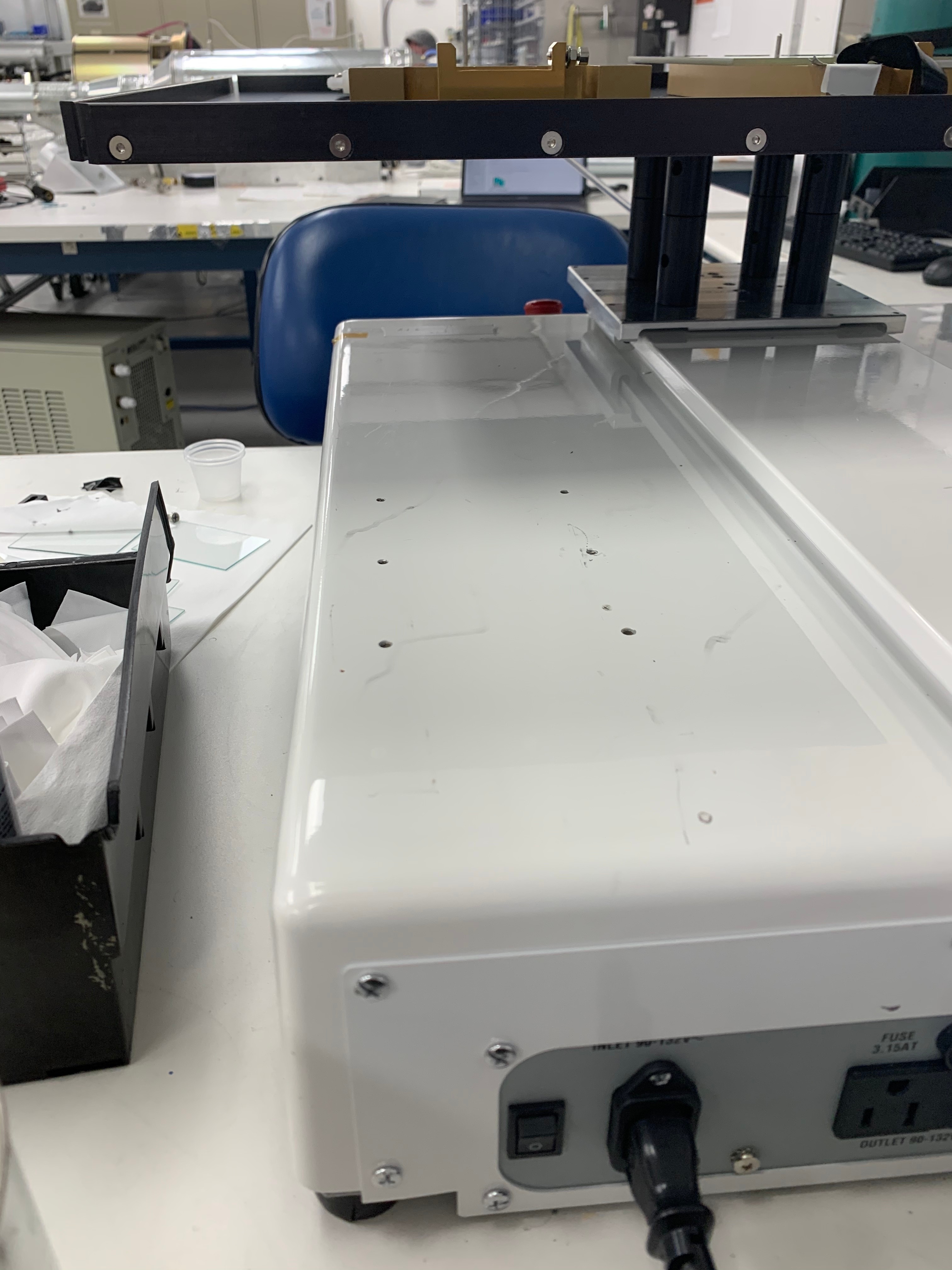
- Turn on glue robot.
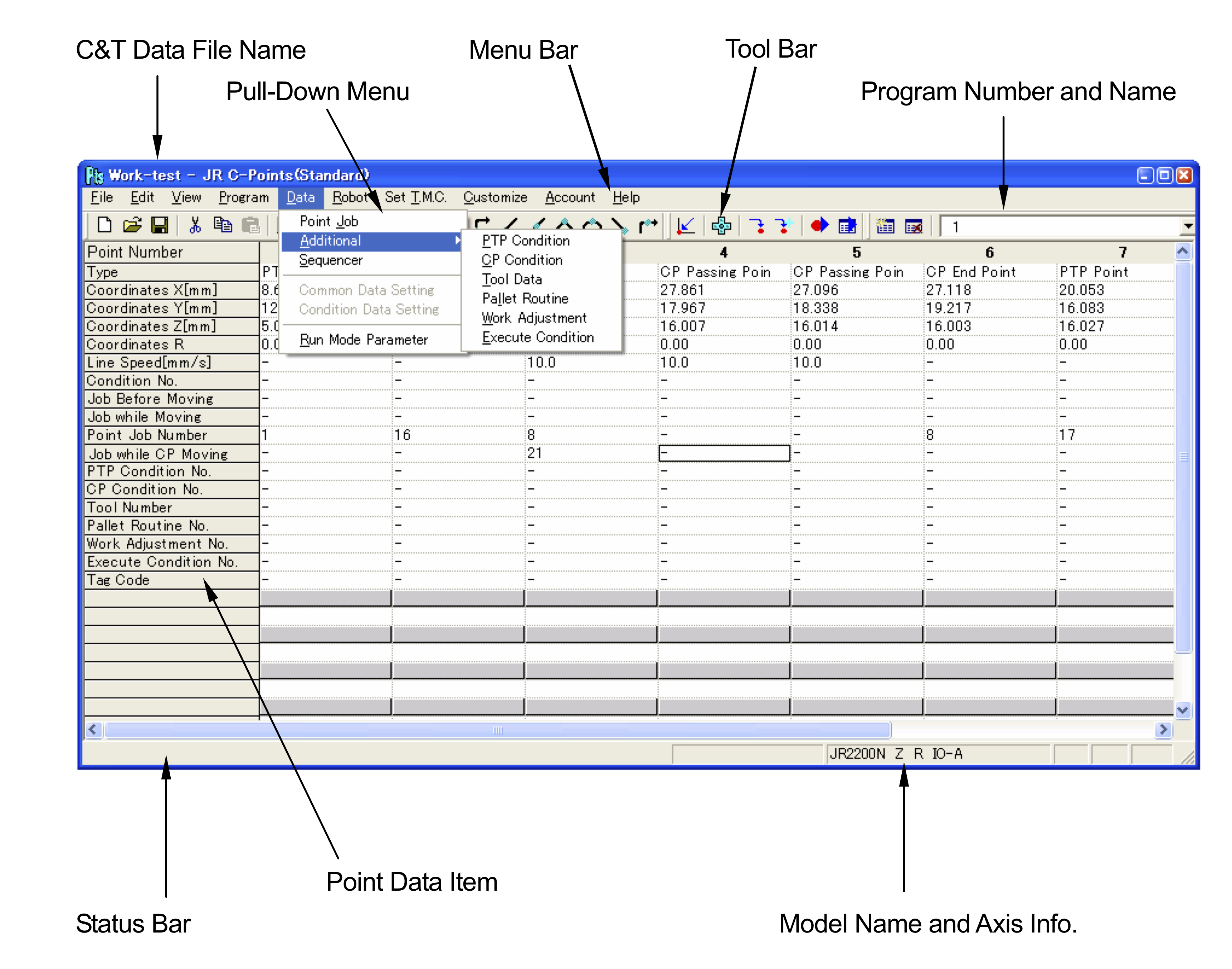
The Itk account on the PC has the Janome Points software installed to control the robot.
The password is AtlasItkBox. For info about the itk-admin account contact Matthias Wittgen
- Click on the desktop icon JR C-Points to start the program

- If a window is shown - please select the following options to initialize the program :
- JR2500-N bullet
- z-axis control
- R-axis control (not ticked!)
- IO-A (not ticked)
Open the file
Neha_2020Feb3_InnerRingx3.cpdit should be the most recent file select the program #The program # is displayed on the right.

We are using the program #13 for the triplet in a row.
Note that the pallet routine is #22 (plane, with auto-increment)
Initialize the robot with
Meca Initialize: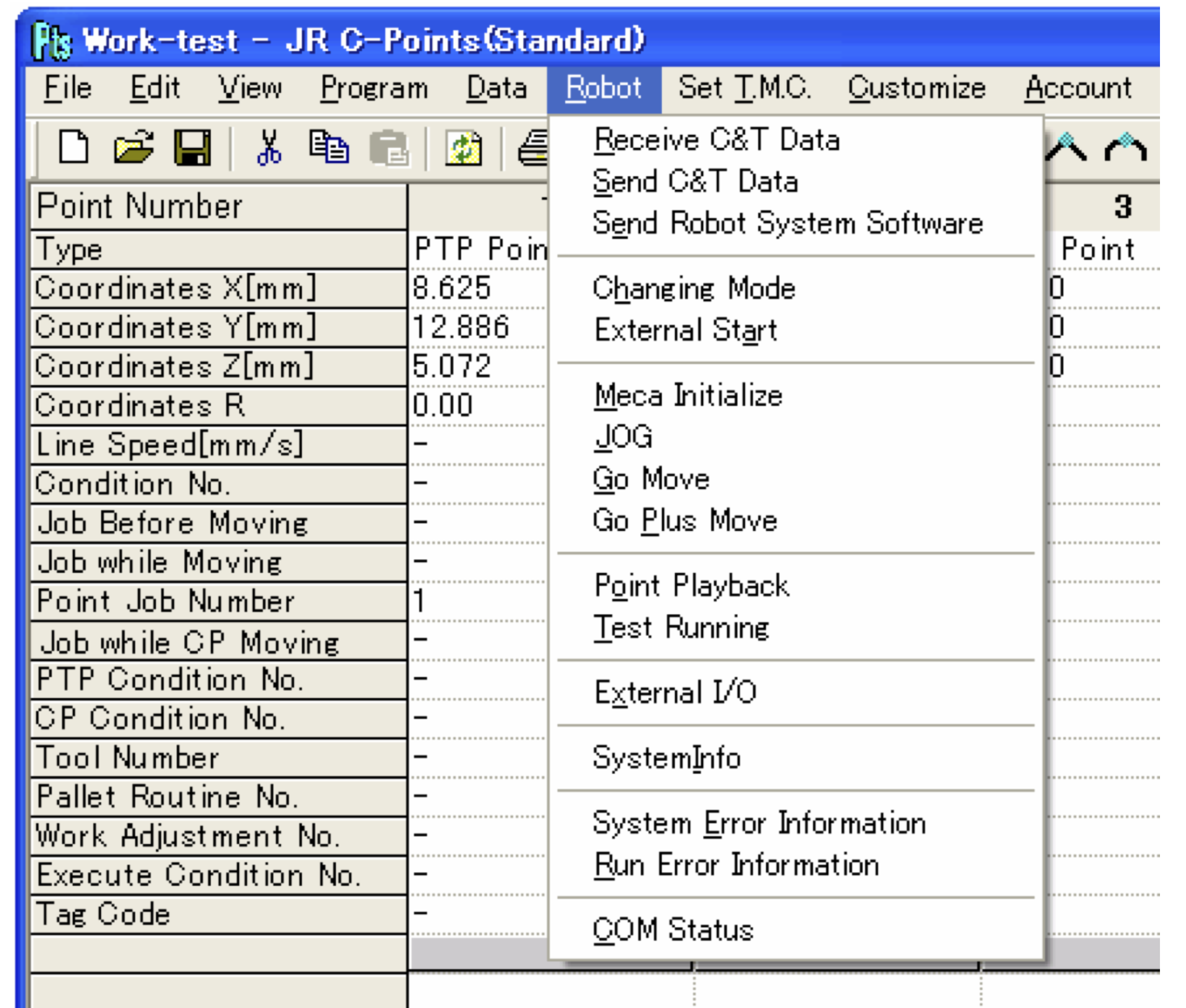
Verify that the z position is placed correctly by using the Tool option to verify the PTP point – hit Go and don't hit Register until you are sure about you want to update the xyz position.
To execute the program hit
Send C&T datafrom the Robot menu.Make sure that the Robot is set in
Teaching modein theChanging Modewindow from the Robot menu.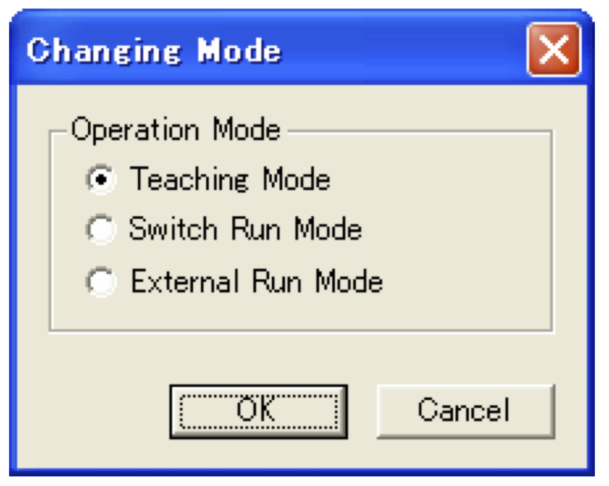
Select Switch Run Mode in the
Changing Modewindow from the Robot menu.Select the program # to execute from the Robot command buttons. It will be displayed on the LED.
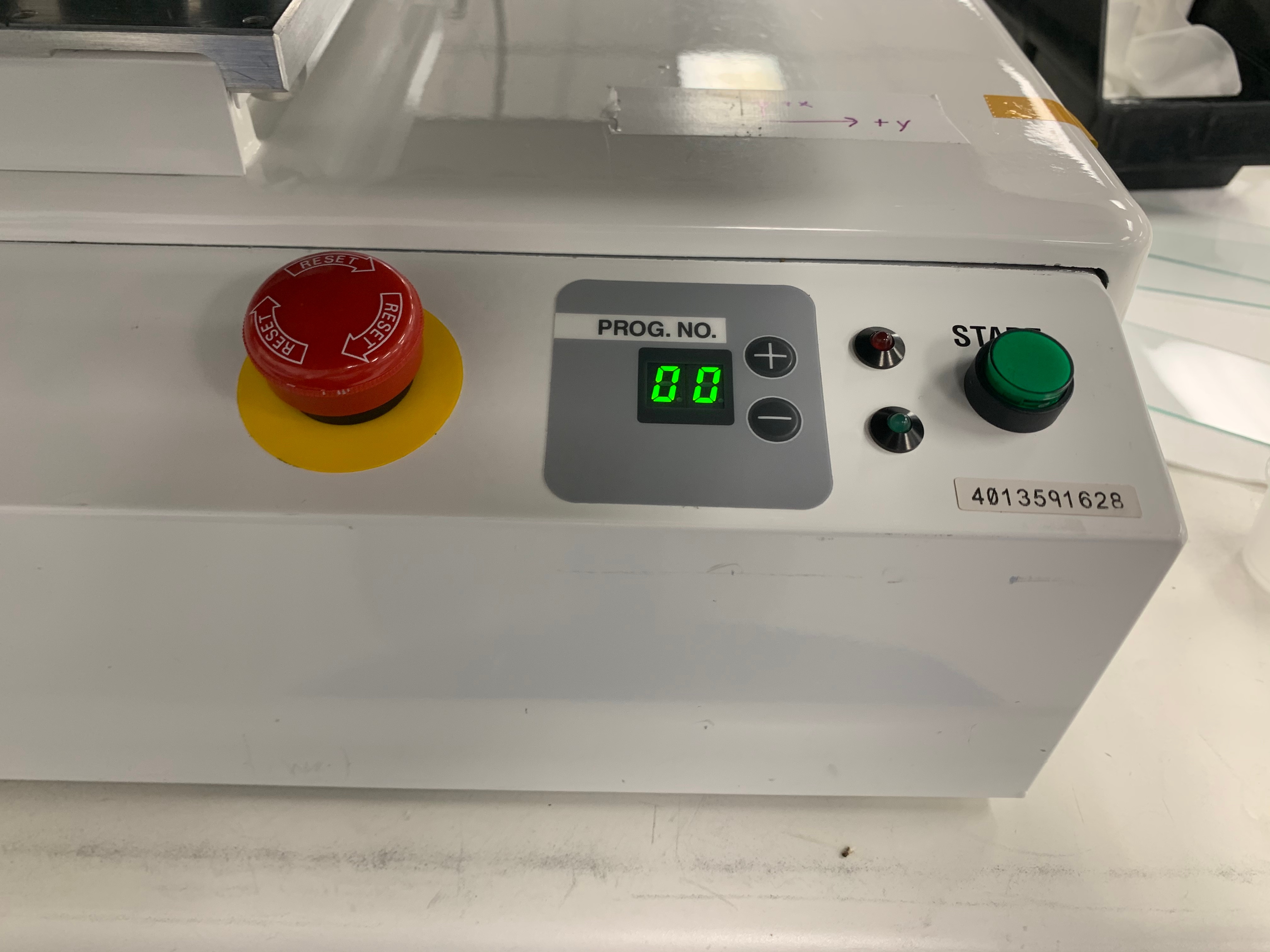
Make sure to use the same # selected in point 7.
Push the green start button.
At any moment if any issue to terminate push the RED button
- To repeat :
- switch to
Teaching modein theChanging Modewindow from the Robot menu. - made the proper changes to the program
- restart from #9
- switch to
- To terminate - before you leave the station:
- Bring the robot back in the original position with
Meca Initialize - Shut down the robot
- Shut down the EFT
- Turn off the valve
- Terminate the program
- Shut down the screen only of the PC
- Bring the robot back in the original position with
Related articles
Glue deposition procedure
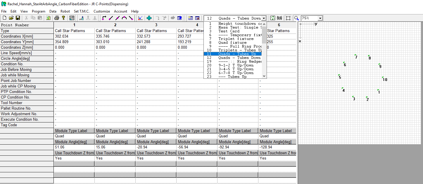
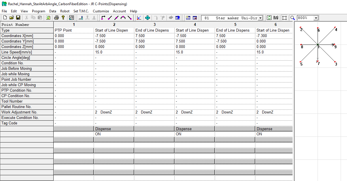
Program file name: Rachel_Hannah_StarAtArbAngle_CarbonFiberEdition
A single JRC program file may contain many programs. A complete glue deposition program contains program data and a point data array specifying where to take actions. The actions themselves are encoded in point jobs. The confluence page Building 33: Programming and using the glue robot breaks down some key concepts. Further information is in the JR-C manuals, linked for download at {gotta upload them}
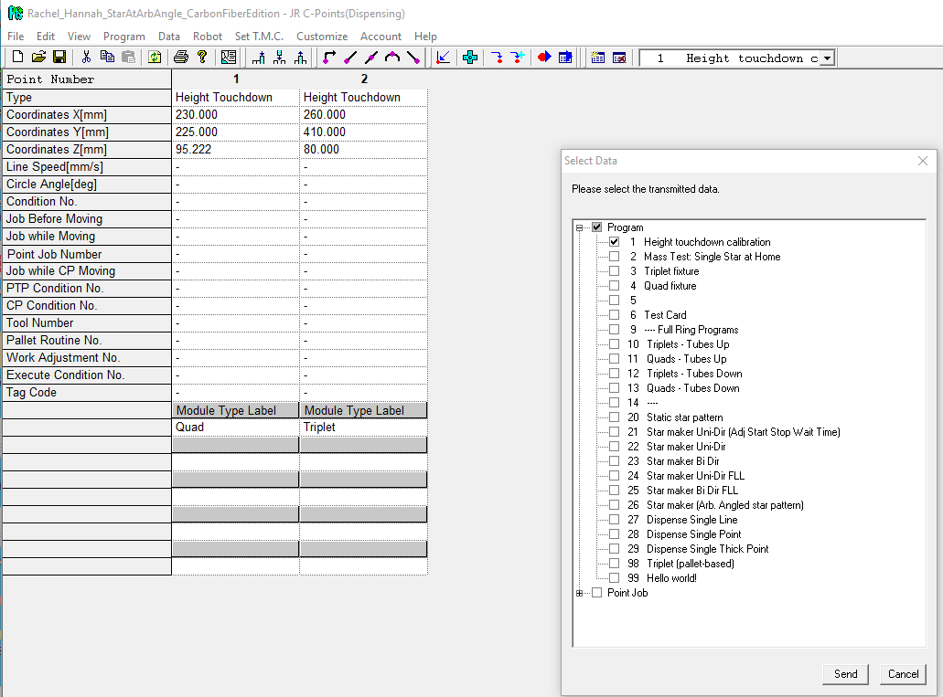
| You can view the complete list of programs using the drop down program menu in the Toolbar. Program numbers with names beginning "----" are actually empty. Those program numbers serve as visual dividers so that we can comment the program menu. |
|---|
Program list & purposes
Calibration programs
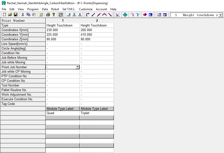
| View when opening program
|
|---|---|
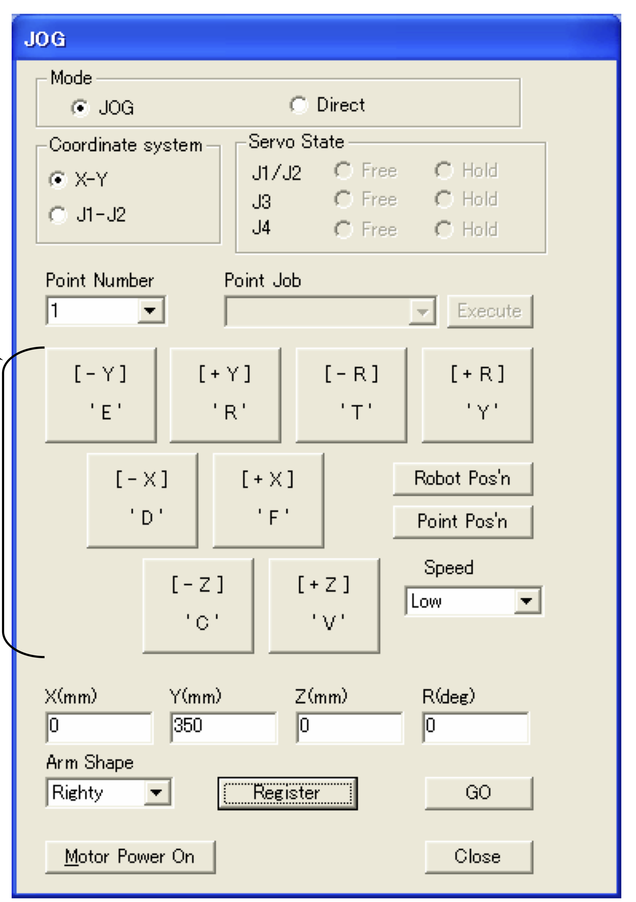
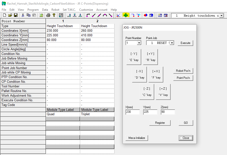 | Use the Jog Panel to descend in Z (Jog panel icon on menu bar highlighted in yellow)
|
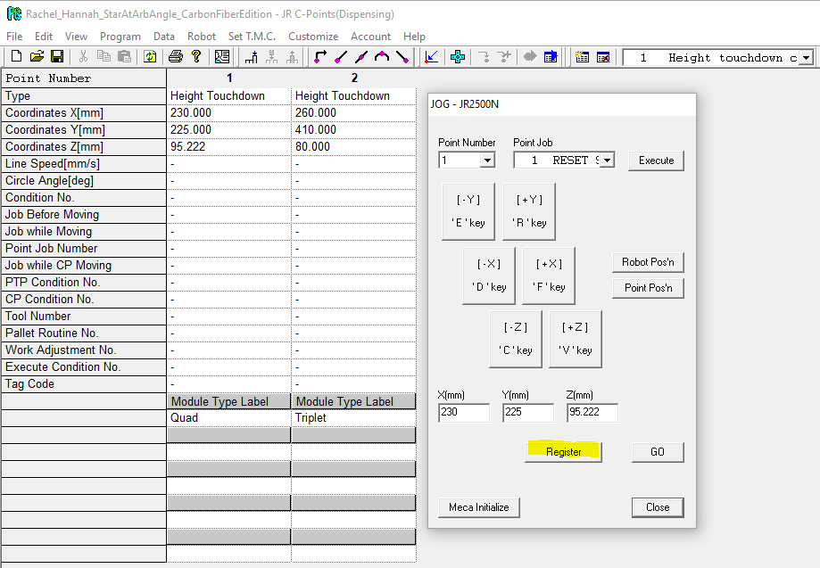 | When touched-down at desired Z and the syringe is secure, "register" your coordinates to Point Number 1 (Quad position).
|
| Segment-send Program #1 Height touchdown calibration to teach the calibrated Z coordinate to the robot
|
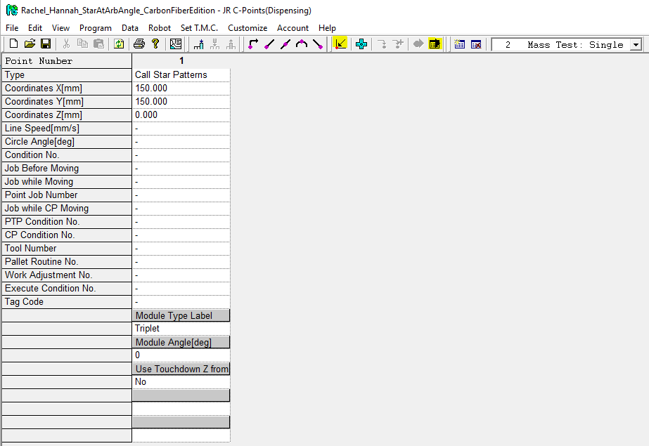
| Program #2 contains a single entry in its point data array, with custom point type "Call Star Patterns." The purpose of this program is to dispense the star pattern's glue into a test cup so we can weigh it and estimate how much glue is dispensed while mounting modules.
You can always meca-initialize ("home") the robot and run the program using the yellow-highlighted menu bar buttons. |
|---|
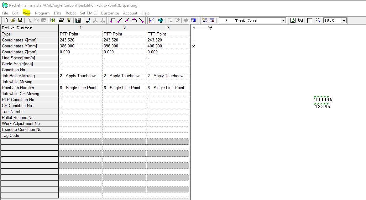
| Program #3: Test card dispenses a set of standardized lines and dots at the triplets temporary baseplate. The purpose of this program is to produce comparable test cards for every syringe we use, so that we can track our "Call Star Patterns" and "Star maker" parameter performance over time. The test card should always be dispensed with the same Pressure (2.0 PSI) and Vacuum (5" H20) settings in order for the results to be comparable between cards. Very viscous glue syringes will result in thin, often broken lines, while very runny glue will result in thick lines and very large dots. The program dispenses five parallel lines, and two rows of five parallel dots. The lines are drawn with the same conditions (linespeed, wait(start), wait(end), upZ, and upZ speed) as the lines in the star pattern. However, note that the lines are longer than those of the star pattern. The upper row of dots is drawn with the same parameters as the lines in the star pattern, though since no distance is traversed during the dot dispensing, the linespeed will not factor in to the dot size or shape. The dot is dispensed for the length of the wait(start) and wait(end) time combined; no additional dispense time is added. The second row of dots is drawn with nearly the same conditions as the first, except that the robot adds an extra one second of dispense time at the dot location. The purpose of the extra dispense time is to obtain a larger sized dot, which may be easier to compare by eye between test cards. You can access the visual representation of the point data array coordinates at any time using View (highlighted in yellow) > Visual display. This program also pulls the relevant Z coordinate from Program #1, and as such, the Z coordinates of the PTP points should be left at 0. |
|---|
Configuration layer programs
Configuration layer programs tell the glue dispensing robot where to dispense a particular glue pattern. The glue pattern itself is stored in other "painter" programs.
Program #6 is a blank program, serving as a visual divider between calibration-oriented programs and the Temporary Fixtures series (programs 7 and 8)
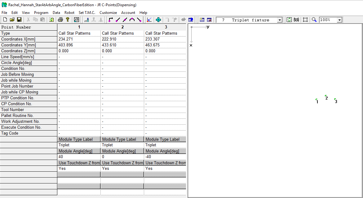
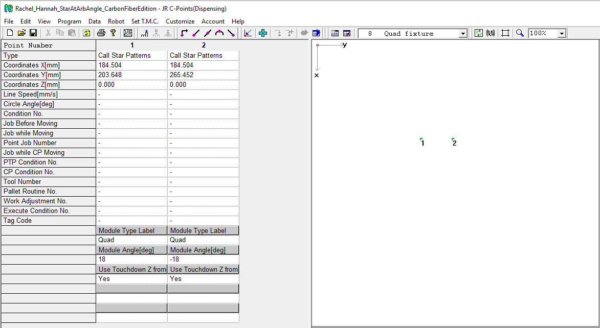
| Program #7: Triplets fixture | Program #8: Quads fixture |
|---|---|
|
|
Program #9 is a blank program, serving as a visual divider between the Temporary Fixtures dispensing series and the Full Ring dispensing series. Each member of the Full Ring dispensing series dispenses all triplets or quads on one side of the ring local support with pause. There are three programs:-
- Program #10: Triplets - Tubes Up/Down (the position data does not change for triplets when we flip the ring)
- Program #11: Quads - Tubes Up
- Program #12: Quads - Tubes Down
The positions populating the point data array come from the "Ring base plate and its coordinate system" documentation developed by Charlie and Scott. The order in each Full Ring dispensing series program corresponds to the module numbering they defined.
|
|---|
| Example: Program #10: Triplets - Tubes Up/Down |
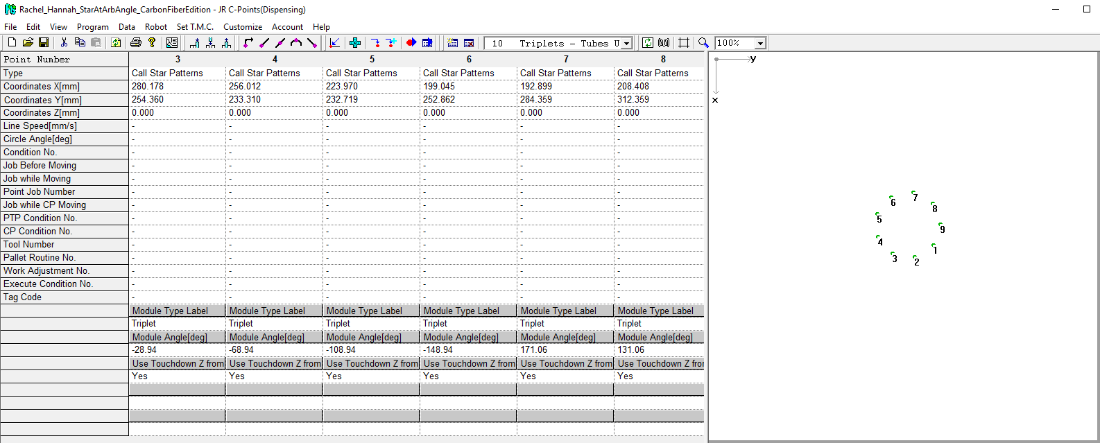
Rather than dispense a full ring, we can dispense the ring one "wedge" at a time, dispensing glue for a set of modules mounted using a single bridge pick up tool. The "Ring base plate and its coordinate system" documentation developed by Charlie and Scott establishes the module numbering scheme. Scott confirmed the module set groupings over email in March 2021. The "Tag Code" entries in the point data array note the module number for which that point data entry dispenses glue. The relevant module numbers are also identified in the program names.
Programs #19, 23, and 30 are intentionally blank programs, serving as visual dividers. The Ring Wedge programs come in three sets:-
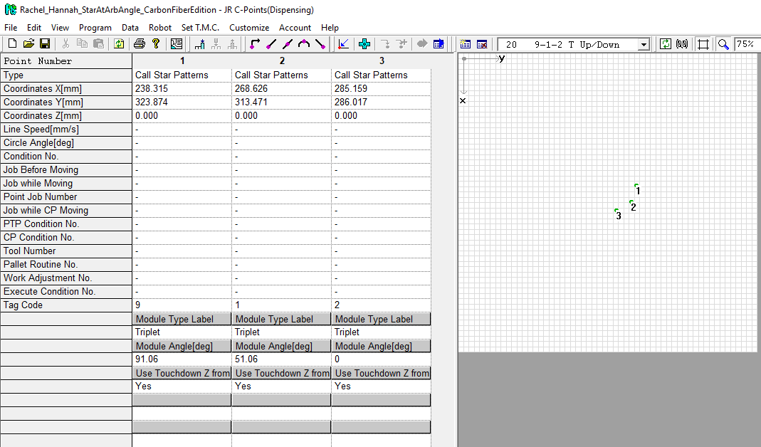
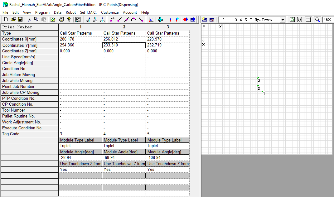
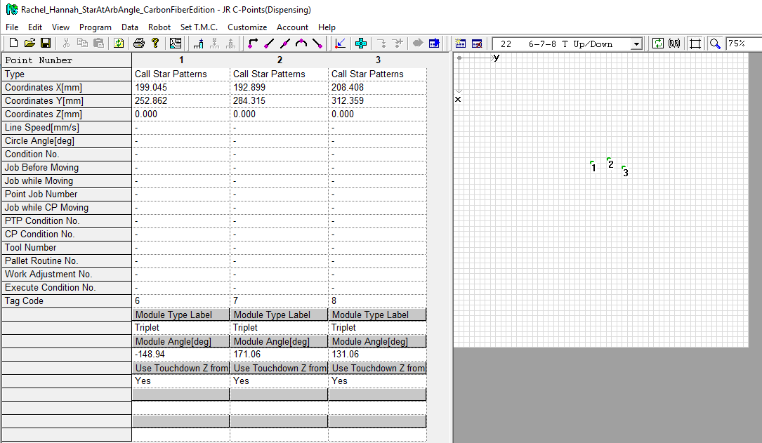
- Programs 20-22 Triplets Tubes Up or Down, abbreviated "#-#-# T Up/Down," where the # signs are stand-ins for the module numbers in the set.
- Programs 24-28 Quads Tubes Up, abbreviated "#-# Q Up," where the # signs are stand-ins for the module numbers in the pair.
- Programs 34-38 Quads Tubes Down, abbreviated "#-# Q Down," where the # signs are stand-ins for the module numbers in the pair.
When using these programs, you must use the full set to dispense all the triplets/quads for that side of the ring. For example, to load the ring with the tubes pointed up, I need to run either programs 10 and 11 from the Full Ring dispensing series or programs 20, 21, 22 (triplet wedges), 24, 25, 26, 27, and 28 (quad wedges) from the Ring Wedges series.
|
|
|
|---|---|---|
| Program 20: 9-1-2 T Up/Down | Program 21: 3-4-5 T Up/Down | Program 22: 6-7-8 T Up/Down |
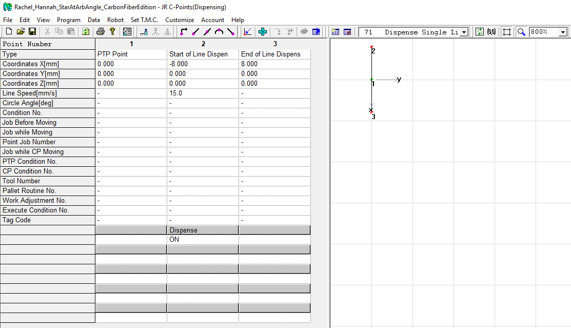
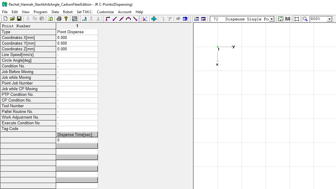
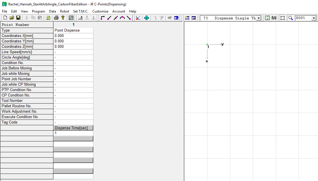
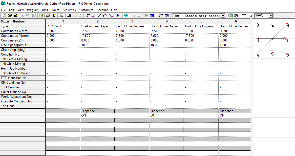
Painter programs
Painters are all relative programs, designed to be called as sub-routines from calibration or configuration layer programs.
|
|
|
|---|---|---|
Debugging programs
We reserve program numbers greater than 90 for testing and debugging purposes. Do not expect to use these during normal operations.