Introduction
Front Panel
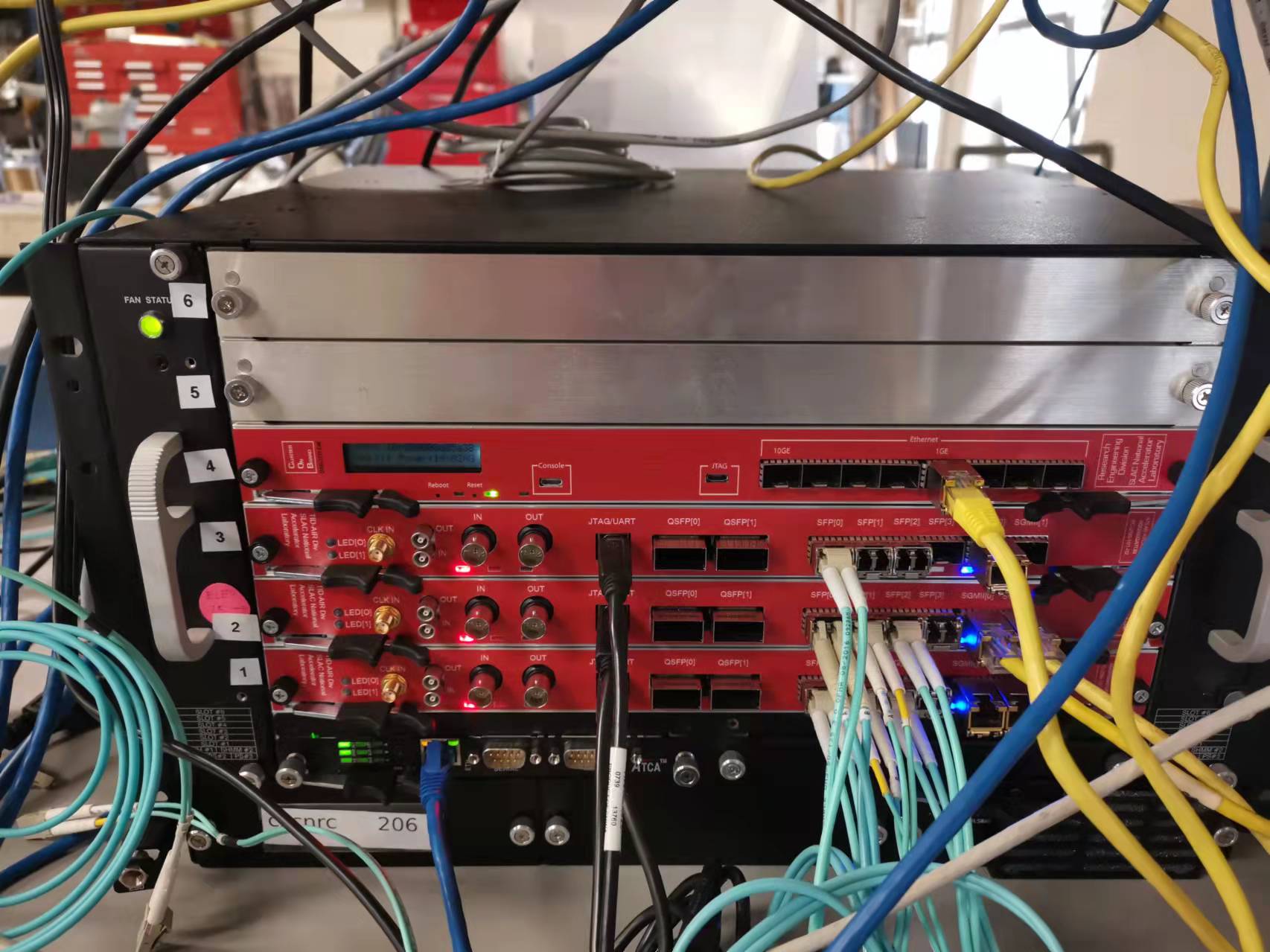
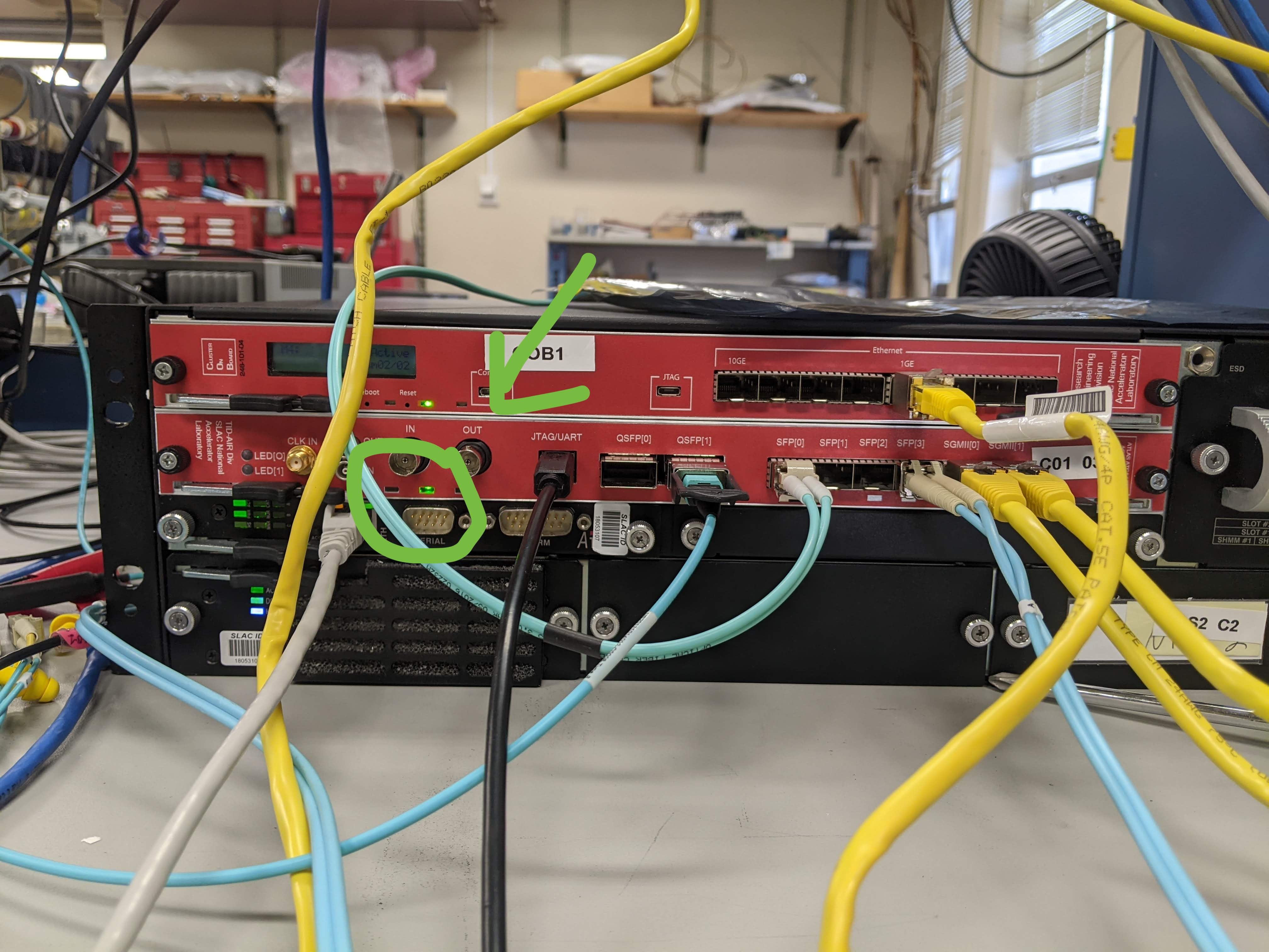
From bottom to top, this ATCA crate has 6 slots in total. The slot 1, 2, 3 have the linkAgg board, while the slot 4 has COB (RCE-Gen3).
For the linkAgg board front panel, there are 4 different interfaces:
1) 2x SFP Ethernet (yellow ethernet cable): used for slow controlling the linkAgg FPGA internal register;
2) 4x High speed SFP+ : optical fiber cable (cyan cable) connected to backend DAQ. Speed depends on the protocol. For example, lpGBT protocol is 10Gbps, Pgpv4 is 6Gbps;
3) 2x High speed QSFP+: 1x QSFP+ port is equivalent to 4x SFP+; all others are same as SFP+ ports;
4) JTAG (USB type A black cable): to program the linkAgg FPGA.
If the linkAgg front panel is properly installed, the leftmost LED should be GREEN, not RED. In particular, the black tab on the right needs to be pressed firmly against the crate - there is a switch inside that needs to be activated in order for the linkAgg to work. Try pushing at different locations along the front panel if you still cannot get the LED to go green.

RTM

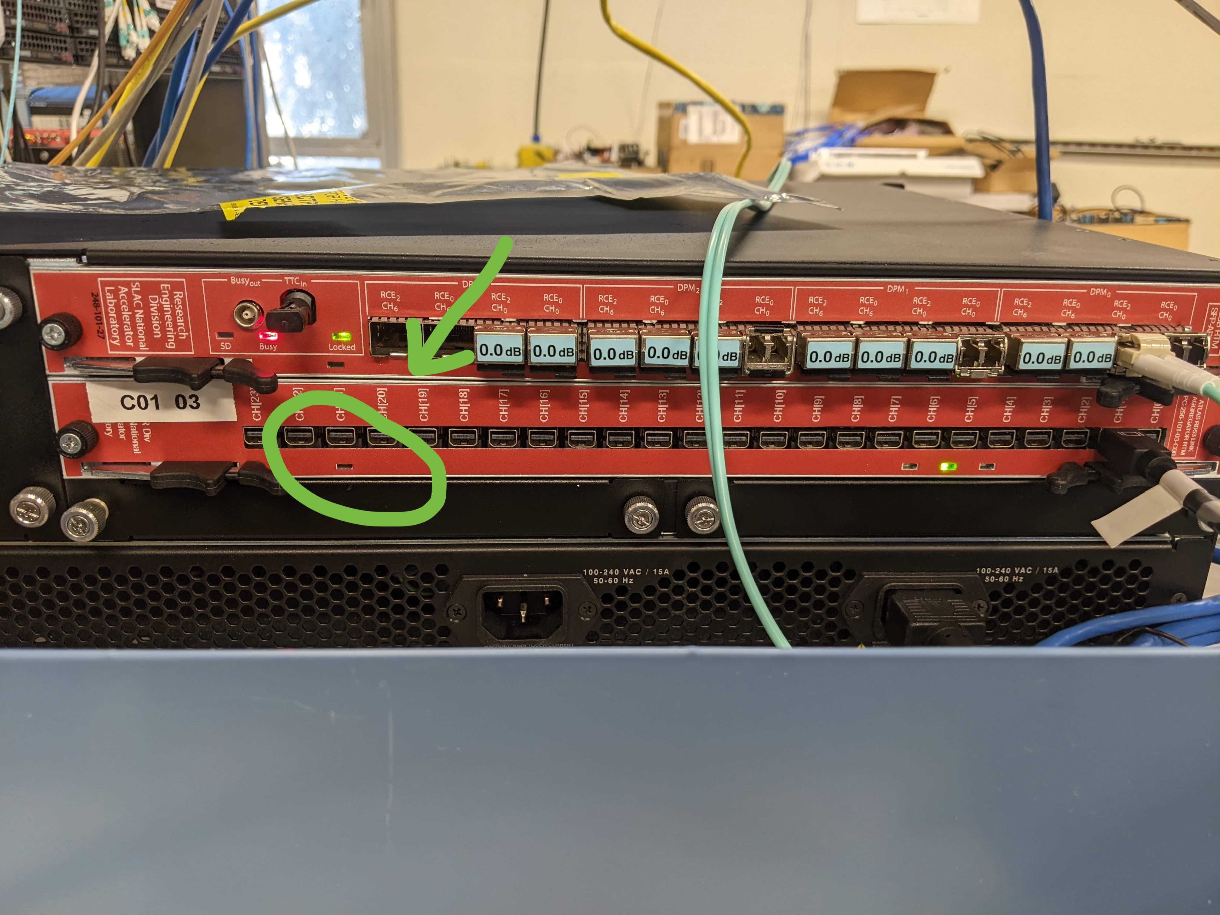
The bottom 3 RTMs are the 24x mDP version RTM for the linkAgg. The top 2 RTMs are the 4x ERM8 version RTM for the linkAgg; the top 3rd RTM is the sfp+ RTM for COB/RCE DAQ.
The mDP version RTM, from right to left is the mDP port 0, 1, 2, ..., 23. (The label CH[X] is not good. The X is right, but CH is confusing people as "channel". Please understand that here CH means a single mDP connector. Each mDP connector includes 4 data lanes, and 1 Cmd lane)
If the RTM is properly installed, the leftmost LED should be OFF, not BLUE. NOTE: Because the RTM is actually a bit shorter than it should be, you need to also deliberately press hard on the right side of the RTM (near the green LED) until you hear a CLICK. This needs to be done every time you remove either the RTM or the front panel. You cannot rely on the lights on the RTM/front panel to indicate whether this has been done properly.
Useful IP Addresses
LinkAgg board
the ATCA board hardware project page: https://confluence.slac.stanford.edu/display/AIRTRACK/PC_256_101_02_C01
RTM hardware project page: ATLAS: RD53
Modification on CMD for RTM (link): we have 3 RTMs after modification (at Epp lab)
| linkAgg Board # | MAC 4 | IP 1 | MAC 5 | IP 2 | hardware description | Test status |
|---|---|---|---|---|---|---|
C01-01 | 08:00:56:00:4f:82 | 192.168.4.66 | 08:00:56:00:4f:83 | 192.168.4.67 | ATLAS ATCA Link Aggregator Board C01-01 - HWDB 267390223 | |
| C01-02 | 08:00:56:00:4f:88 | 192.168.4.72 | 08:00:56:00:4f:89 | 192.168.4.73 | ATLAS ATCA Link Aggregator Board C01-02 - HWDB 267390220 | |
| C01-03 | 08:00:56:00:4f:8e | 192.168.4.78 | 08:00:56:00:4f:8f | 192.168.4.79 | ATLAS ATCA Link Aggregator Board C01-03 - HWDB 267390217 | In testing |
*Note 1), there are 2 IPs for each linkAgg board. User can use one IP for the rogue GUI software to access the FPGA FW status, and another IP for the back-end DAQ to access the FPGA FW status.
*Note 2), the MAC 4 and MAC 5 are for the two front-panel ethernet ports, and MAC0-3 are for the ATCA fabric backplane, which we are not using so far
*Note 3) need to program the firmware to get the ethernet connection
*Note 4) in b33 the IP will be 192.168.1.* instead
ATCA crate
| ATCA Name | IP | Location | access |
|---|---|---|---|
| 6-Slot ASIS | 192.168.4.2 | B84, room B231 (lab C) | root/NA |
| 2-Slot ASIS | 192.168.4.210 | B84, room B231 (lab C) | root/NA |
FPGA firmware for the linkAgg board
the firmware is officially released here: https://github.com/slaclab/atlas-rd53-atca-dev/releases
current lpGBT emulator firmware for linkAgg is AtlasAtcaLinkAggRd53Rtm_EmuLpGbt-0x03010000-20220204084052-ruckman-6bfc5ca.bit
current PGPv4 firmware for linkAgg is AtlasAtcaLinkAggRd53Rtm_Pgp4_6Gbps-0x03010000-20220204084122-ruckman-6bfc5ca.bit
*the XXX.bit file can be used to program the FPGA through the JTAG interface with vivado software
*the XXX.mcs file can be programmed to a permanent memory of the linkAgg firmware, so that the FPGA can automatically get firmware from the memory when power on
Vivado to program the FPGA through JTag interface

Software to slow control the linkAgg Firmware
the rogue-based GUI software is also included in the same github project of the firmware: https://github.com/slaclab/atlas-rd53-atca-dev
in order to run this software, need to install rogue package at first: https://slaclab.github.io/rogue/installing/anaconda.html#
Instruction to install the rogue
install anaconda at first:
$ wget https://repo.anaconda.com/archive/Anaconda3-2020.07-Linux-x86_64.sh
$ bash Anaconda3-2020.07-Linux-x86_64.sh


Use the following command to add anaconda to your environment. This can be added to your .bash_profile.
$ source /path/to/my/anaconda3/etc/profile.d/conda.sh
install rogue enviroment:
$ conda create -n rogue_5.6.5 -c tidair-packages -c conda-forge -c pydm-tag -c tidair-tag rogue=v5.6.5
(rogue 5.6.5 is verified to work with the GUI software. New version may fail)
Enable the rogue enviroment
$ conda activate rogue_5.6.5
Download the linkAgg github project
$ git clone --recursive git@github.com:slaclab/atlas-rd53-atca-dev
or
$ git clone --recursive https://github.com/slaclab/atlas-rd53-atca-dev.git
Run the software
$ cd atlas-rd53-atca-dev/software/
$ python3 scripts/gui.py --ip <IP add> --remoteDevice <firmware_type>
the firmware_type is LinkAggLpGBt or LinkAggPgp or Kcu105 or Zcu102. You can find the IP address from here: linkAgg boards IP
For example, python3 scripts/gui.py --ip 192.168.4.72 --remoteDevice LinkAggLpGBt

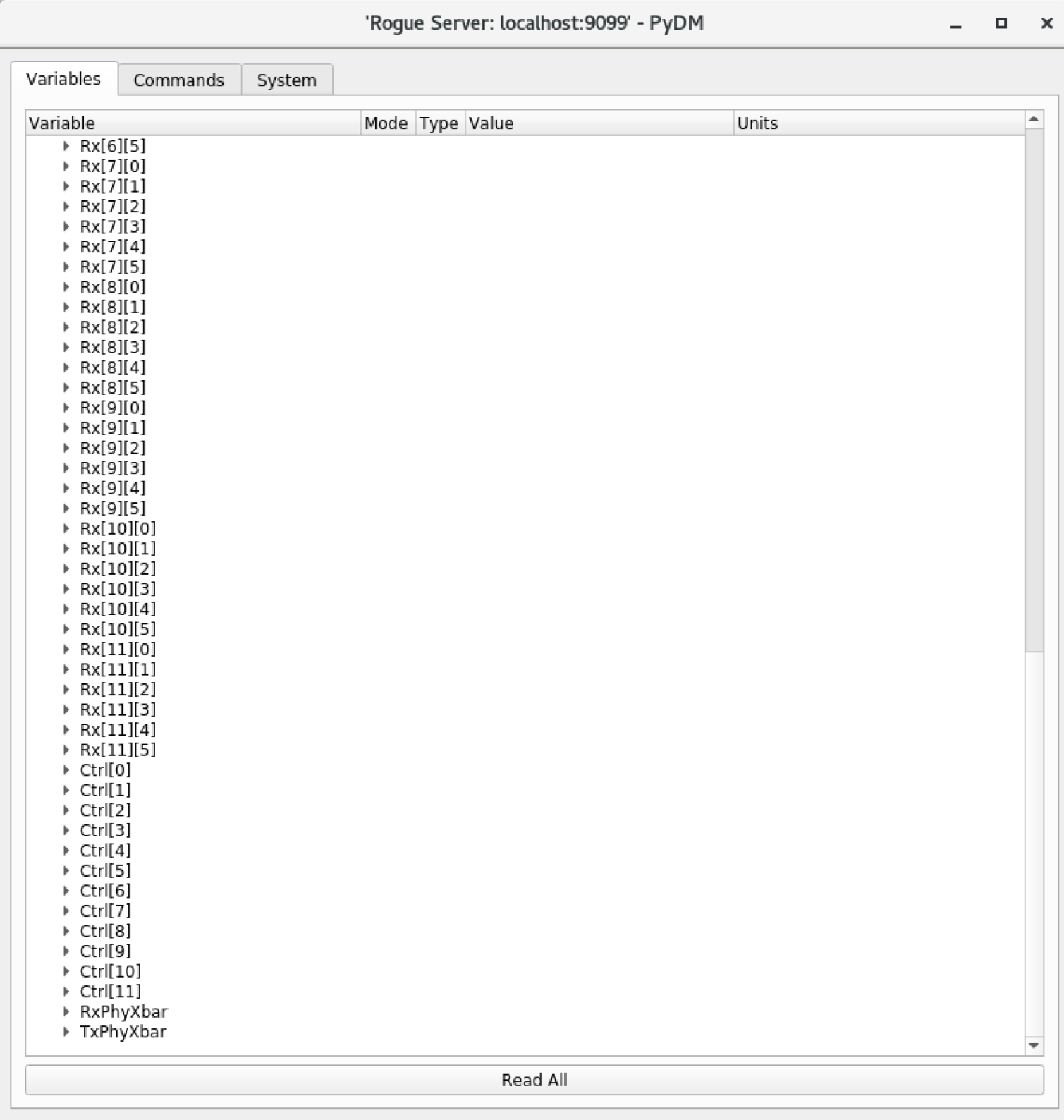
The Rx[A][B] is for the E-link (1.28Gbps data from Rd53). Each lpGBT protocol can have up to 6 E-link, so, B value from 0 to 5. LinkAgg board has 12 optic-fiber output, so, A value from 0 to 11.

The 12x Ctrl are for the 12 optic-fiber interface ( 4x SPF+ and 2x QSFP+)

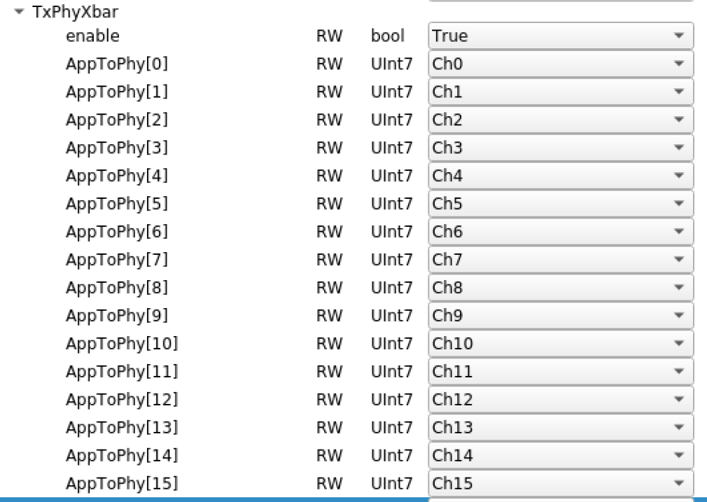
this lpGBT-emulator firmware can re-mapping the lpGBT E-link and physics data lane on the RTM (RxPhyXbar), and lpGBT E-Cmd and physics Cmd lane on the RTM. (real lpGBT chip can not, the lpGBT E-link/Cmd are hard-cored with physics data/cmd lanes)
A simple diagram to show the correlation of the SPF+/QSFP+ to "ctrl" and mDP to "Rx Phy Ch". Note: this is for the lpGBT setup only.
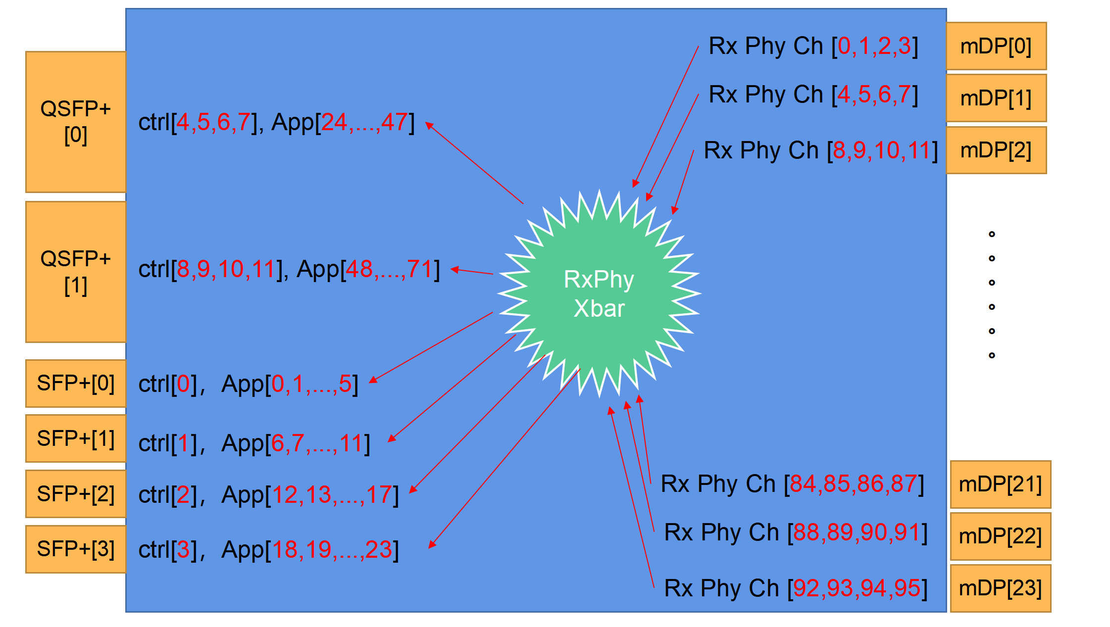
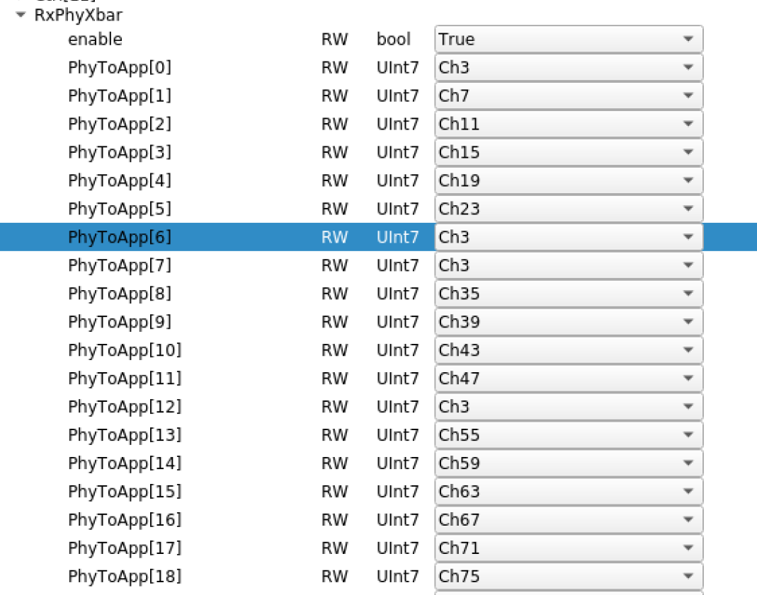
The RxPhyXbar can randomly remapping the connection between App[x] and RxPhyCh[y]. For example, see below:
the Ch3 is from the mDP[0]. It could be mapped to multiple App[X], for example, is mapped to App[0, 6, 7, 12].
App[0] is connected to ctrl[0]; App[6, 7] are connected to ctrl[1]; App[12] is connected to ctrl[2].
The Rx[0][0] is used to control the App[0]; Rx[1][0] for App[6]; Rx[1][1] for App[7]; Rx[2][0] for App[12]. For any App[X], it is connected to ctrl[ int(X/6) ], and the Rx[ int(x/6) ][ (x%6) ].
When there is a stable 1.28Gbps data from Rd53a on the phy Ch3, we can see linkUp=0x1 on Rx[0][0], Rx[1][0], Rx[1][1], and Rx[2][0], like below:

Pgp setup
For the Pgp setup, each ctrl is linked to 4 apps. Each SFP controls two ctrls and each QSFP controls four ctrls. So for example using the default mapping,
SFP[0] controls ctrl[0] (use tx/rx = 0 in the module connectivity) and ctrl[1] (tx/rx = 1)
SFP[1] controls ctrl[2] (tx/rx = 0) and ctrl[3] (tx/rx = 1)
...
QSFP[0] is uses 4 fiber optic cables, each of which has a label on the physical cable
Fiber 1 controls ctrl[8] (tx/rx = 0) and ctrl[9] (tx/rx = 1)
Fiber 2 controls ctrl[10] (tx/rx = 0) and ctrl[11] (tx/rx = 1)
etc...
Mapping for Pgp4:
For mapping ctr: each ctr has 4 App
SFP0 controls ctr 0 (Rx/Tx 0), 1 (Rx/Tx 1)
SFP1 controls ctr 2 (Rx/Tx 0), 3 (Rx/Tx 1)
SFP2 controls ctr 4 (Rx/Tx 0), 5 (Rx/Tx 1)
SFP3 controls ctr 6 (Rx/Tx 0), 7 (Rx/Tx 1)
QSFP0 related to 4 fiber (have labels on top)
- Fiber 1 controls ctr 8 (Rx/Tx 0), 9 (Rx/Tx 1)
- Fiber 2 controls ctr 10 (Rx/Tx 0), 11 (Rx/Tx 1)
- Fiber 3 controls ctr 12 (Rx/Tx 0), 13 (Rx/Tx 1)
- Fiber 4 controls ctr 14 (Rx/Tx 0), 15 (Rx/Tx 1)
QSFP1 related to 4 fiber (have labels on top)
- Fiber 1 controls ctr 16 (Rx/Tx 0), 17 (Rx/Tx 1)
- Fiber 2 controls ctr 18 (Rx/Tx 0), 19 (Rx/Tx 1)
- Fiber 3 controls ctr 20 (Rx/Tx 0), 21 (Rx/Tx 1)
- Fiber 4 controls ctr 22 (Rx/Tx 0), 23 (Rx/Tx 1)
Note that in addition to changing the tx/rx in the module connectivity, you also need to change the "port" and SFPPortFrontPanel variables in the controller file to equal the tx/rx value.
2 Comments
Alex Wang
Nice writeup!
Useful set of slides: https://indico.cern.ch/event/359387/contributions/
Alex Wang
Useful CERN TWiki: https://twiki.cern.ch/twiki/bin/view/Atlas/RCEDevelopmentLab