General Strategy and Infrastructure
The interlock is needed to stop the power during three conditions, overheating, over cooling, and condensation. The system relies on temperature data from the modules them selves provided by an onboard NTC thermistor, RTD thermistors located at key points and humidity sensors. The data from all these sensors is read into the influx database which can be readout by grafana.
Module Q/C Lab Testing Interlock
Setup:
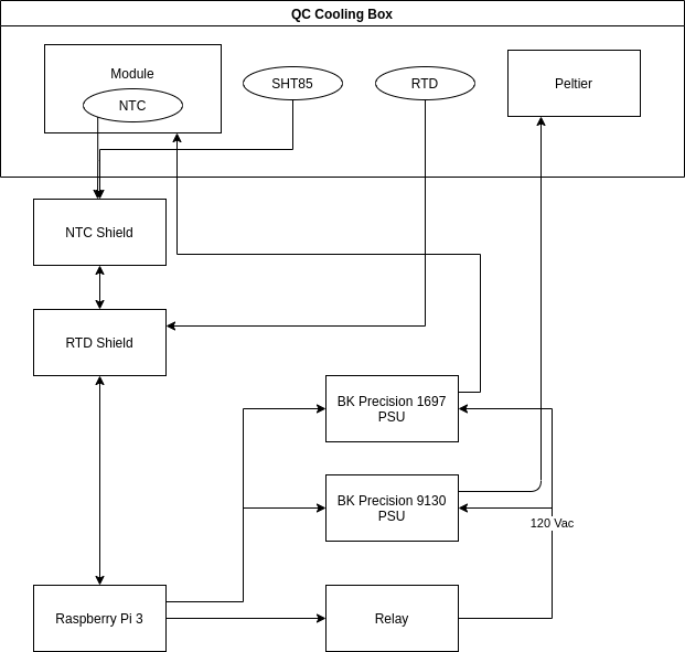
The interlock is run off an raspberry pi 3 with two shields capable for reading in the three kinds of sensors used. The pi contentiously monitors the temperature, dew point, power settings. The raspberry Pi is also used for the digital control system.
Pi Software:
All the software for this Pi can be found at https://gitlab.cern.ch/nyoung/dcs-interlock/-/tree/Pi_only
Interlock:
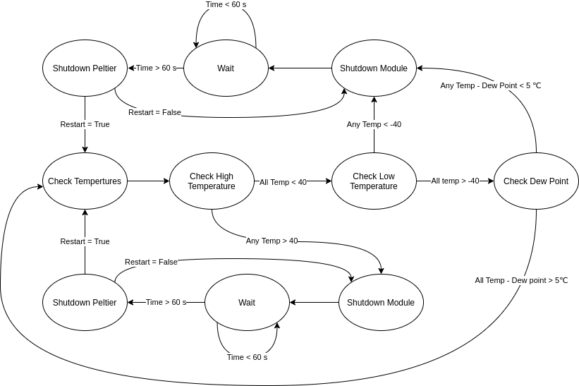
The python module "Interlock_SW.py" makes all the high level decisions about the interlock. The trigger temperatures are set at 40℃ and -40℃ the triggers can be set by the variables
- On_Module_High_Limit: sets the high limit temperature to shut everything down.
- On_Module_Low_Limit: Sets the low temperature limit that shuts the system down.
- DewPoint_buffer: Sets the difference that once a single temperature value is within this amount it will shut the whole system down.
- Restart: If true this will allow the system to try and automatically restart itself if something goes wrong. If False the system will just shut down and endless send the off signal to the power supplies.
Interlock Finite States:
The interlock is not coded as a finite state machine but applicably works as shown below.
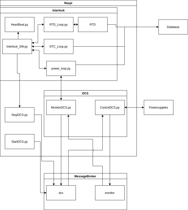
Sub modules:
Interlock
- Main Interlock Loop: This main part of the code controls all the decisions of if the system is in a safe state. It checks all the measurements and makes sure that they are all within normal operating specs. Note that there is four options at the top the four options are
- RTD_SHT85_Loop: This loop runs the code to monitor the RTD’s every few seconds. This is needed since the packages to monitor them are in Python 2.7 and everything else is in python 3
- RTD_SHT85: Read the RTD sensors and SHT85 then pass the information back to the main process to decide if things should stay. This process also writes the data to the influx database
- NTC_Loop: Again read over all the NTC values and return the info to the main loop.
- HeartBeat_py: This piece of the code runs to make sure that the Main loop is still working properly. It checks the time since the last updated system. If the time passed is too long the heartbeat will turn off the relay and make sure that everything is safe.
Readout System:
DCS
- BK_PSU_DCS.py: This is the serial commands for the two power supplies that are used. Note that in order to work the address of the power supplies need to be set. The default for BK9130 is 22 and BK1697 is 44.
- ControlDCS.py: This file does the heavy lifting. It subscribes the rabbitMQ queue called dcs. Once a message is posted it either sets the power supplies to that setting or if {“return”: True} then it gets the current settings and posted them to the queue message.
- MonitorDCS.py: Sends the signal for the control to get power supply settings then converts all the from bytes into floats.
- Start_module.py: script to start the module DCS
- Start_peltier.py script to start the peltier.
- stopDCS.py: Send stop command to all the power supplies or you can import the modules and send shutdown to one or the other power supply..
The DCS and the Interlock talk through a message broker on rddev111. This message broker passes dictionaries along. Formatted as
           {"peltier": [{"channel": 1,
                         "power": 'off',
                         "voltage": 10,
                         "current": 1,
                        {"channel": 2,
                         "power": 'on',
                         "voltage": 12,
                         "current": 1,
                        {"channel": 3,
                         "power": 'off',
                         "voltage": 10,
                         "current": 0}
                        ]}
            "module": [{"power": 'on',
                        "voltage": 10,
                        "current": 1.4,
                       ]}
             }
Where all voltages are in volts and all currents are in amps. The python file to handle the message delivery and receiving is found in RabbitMQ/KombuAdmin.py. The system will only keep a undelivered message for 60 seconds before it drops it. Any system subscribed to the broker will wait up to 60 before it will time out, not causing errors but returning an empty result.
Installation:
to install the Interlock on a new pi copy the SD card of the existing scc_cooling setup. To do this plug in the micro USB card to the USB port on your computer.
sudo fdisk -l
The correct device will be the one listed
sudo dd if=/dev/qc_cooling_pi.img of~=/dev/[sd card location]
Install the SD card into the Pi.
Once the network is setup for the Pi the only thing that needs to be changed in the Interlock is found in the file 'config.json'
{
   "vhost": "qc_cooling1",
   "influx_measurement": "qc_cooling",
   "rtd_channels": [1, 3, 4, 5]
}
"vhost" the RabbitMQ name required for the system to know which setup you are sending and receiving commands from.
"influx_measurement" the title all the influx measurements are stored under. This is important to know when you want to retrieve the data.
"rtd_channels" the list of channel on the rtd board that are being used.
Errors:
There will be no errors as the system works perfectly every time but in the off chance that something mishaps goes wrong logs can be found in the directory
~/log/
B33 Ring/Stave Q/C Setup Interlock
code locations
- /home/nyoung/B33_Interlock/Prototype-Interlock/Prototype-Interlock.ino (Code modified by Nathan Young to output the sensor data to the DB)
- /home/jmoss/Arduino/Prototype-Interlock/Prototype-Interlock.ino (original code written by Josh Moss)