List of CMM Measurements by date
July 29, 2022: Measurement of loaded staves. https://indico.cern.ch/event/1185436/
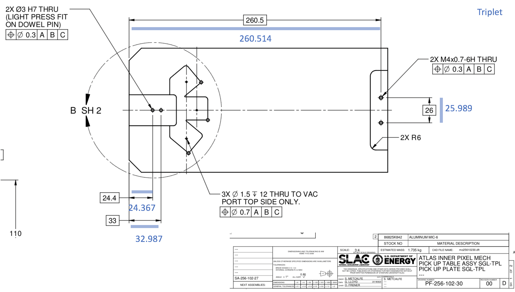
July 26 and July 12, 2022: Measurement of linear triplets: location of resistors defining clear areas: https://indico.cern.ch/event/1185434/
July 12, 2022: Stave Flatness: https://indico.cern.ch/event/1181250/
July 9, 2022: Test-loading of glass on 1-pin stave (19-1) https://indico.cern.ch/event/1185436/
June 21, 2022: Test of glass on glass for the staves: https://indico.cern.ch/event/1179352/ and https://indico.cern.ch/event/1176661/
June 14, 2022: Stave Bridge Metrology: https://indico.cern.ch/event/1176661/
25 February 2021: Checking glass placement with reworked tooling
Over time, the baseplates wore down from friction with the glass coverslips we used for glass-glass tests. Scott and Matt worked with the Machine Shop to update the base plates in February 2021. Neha re-measured them with the CMM in early March 2021. Scott's PDF with the drawings of the updated base plates is also attached here. Scott and Matt noted that the 0.107 mm (6 mil) difference in the distance between the corner in the drawing and the measurements for quads is within tolerance for the pin + edge location.
Hi All,
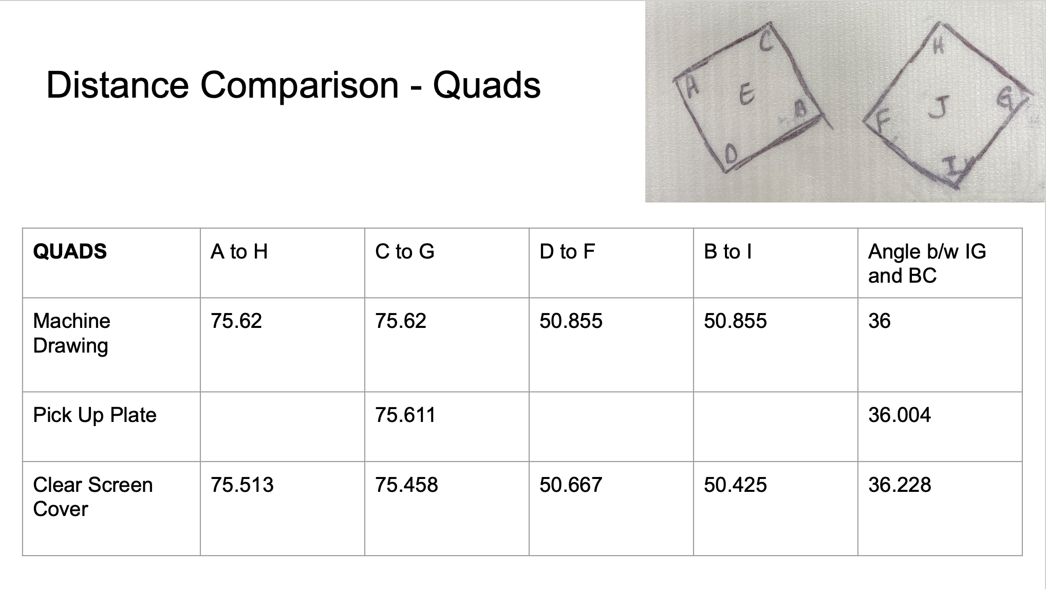
Today I ran some CMM measurements on the quad and triplet pick up plates to verify corner positions, distances, and angles. I've attached two tables below comparing the distance between different corners on the machine drawings (thank you Scott!), the pick up plates, and these clear screen protectors that Hannah and Matt used double sided tape to place glass slides on (named clear screen cover). The lettering scheme I followed was provided by Hannah and I've put a little picture on each slide illustrating it.
Additionally I found the x,y positions of the pocket corners on each plate, as well as the distance between them and the center of the dowel pin (which I used as the origin). I've labelled those below on the machine drawings Scott provided.
Please do let me know if anything is missing/unclear!
Thanks!
Sincerely,
Neha Singh


February 23, 2021: Height measurements for the quad bridge
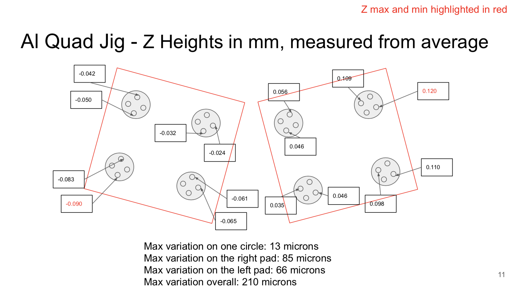
Measurements from Neha & Katy to check the flatness of the vacuum pads on the quad bridge pick up tool. They made these measurements in response to the observations Charlie and Scott made with the CMM concerning the flatness of the quad mechanical modules (see Quad mechanical module properties).
https://docs.google.com/presentation/d/1RSVKcMSFJkuyg1COm5SHbhYQEZUKdEvidnNytE9VIpI/edit?usp=sharing
Scott's commentary
Hi Katy and all,
Thanks for sending this. Agree that tooling height variation and module height variation would tend to add together when vacuum is on. Looking at the numbers below the 3D graphs from the CMM software, I see the software reports "flatness" of .018 for the quad tooling and .023 for the triplet tooling. If I follow what the software is doing, it looks like the flatness is relative to a best-fit plane through the points. For the quad tooling, it looks like the best-fit plane is tilted relative to the CMM horizontal plane. When the quad tooling is placed on the loading tooling, I think this tilt will be different, set by the 3 micrometer adjusters, and with tilt limited by the bushing fit onto the pin. I'd hope for less variation when installed on the loading tooling than what's shown on slide 11, but I have not directly measured this. The .023 flatness (+/- .012 relative to the best-fit plane) would have a little contribution to the glue thickness error but my sense is it's not the largest source of error, so I'd suggest using the quad tool "as is". About the tilt, maybe Matt could comment on how repeatable landing on the 3 micrometer adjusters is, or maybe a CMM measurement could be done using the ends of the 3 adjusters to define a plane then measuring the height of the vacuum pads relative to that plane.
Cheers,
Scott
Oct 29 Measurements of the triplet pick-up plate, compared to machine drawings

October 23, 2020 Measurements of the quad pick-up plate, compared to machine drawings.
Measured values are within tolerances specified in the drawing.
