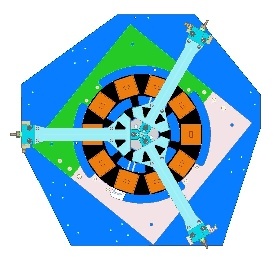
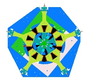
At the SLAC ITk Pixels technical meeting on October 13, 2020, Charlie presented a coordinate system for the ring baseplate. You can find his calculations and coordinate system document at the Indico page here: https://indico.cern.ch/event/960664/
A copy of the coordinate system document is included here as a reference. The calculated coordinates for triplets are the same on either side of the ring, since the rotation of the ring and handling frame accounts for their angular offset. Specifically, the handling frame lines up with a different mark on the base plate. Quads need an additional adjustment, so there are distinct sets of coordinates for the "tubes up" and "tubes down" sides of the rings.
The module center locations in the glue robot coordinate system were recalculated in preparation for dispensing on the 19-0 prototype ring. Measurements of Datums A and B (two edges of the 19-0 tooling used to determine the tooling to glue robot coordinate transform) were taken March 26th by Caterina and Matt. The new module center positions were calculated on March 29th by Rachel, with help from Charlie. The updated spreadsheet listing the Datum measurements, module centers in the tooling coordinate system, and module centers in the robot coordinate system is provided below (glue_robot_coordinates_AllModules_29-March-2021).
Note that the Datum measurements were taken using the edge-finder, which was mounted in the rear slot of the robot dispenser head. As a result, a constant shift of -1.0 inch was applied to the x coordinates measured. The uncorrected measurements are on the far right side of the first two sheets.
The updated module centers were roughly checked by taping the tooling diagram sheets on top of the mounted tooling. Photos were taken of the module centers (with a dry syringe) compared to the paper for each module. These photos can be found in a Google Photo Album here. The module centers appeared to agree with the drawing to within a few millimeters. Note that this method is not a precise test of the module alignment and only serves as a sanity check on the calculations.
We mount modules in sets using loading bridge pick up tools. Scott's drawings reflect this approach.
The bridges are designed to evade the cooling tubes sticking out of the ring local support. Charlie defined a numbering scheme for the modules in his document. Under this scheme, the modules set in each "wedge" are as follows:
| Triplets | Quads |
|---|---|
9-1-2 3-4-5 6-7-8 | 1-2 3-4 5-6 7-8 9-10 |

