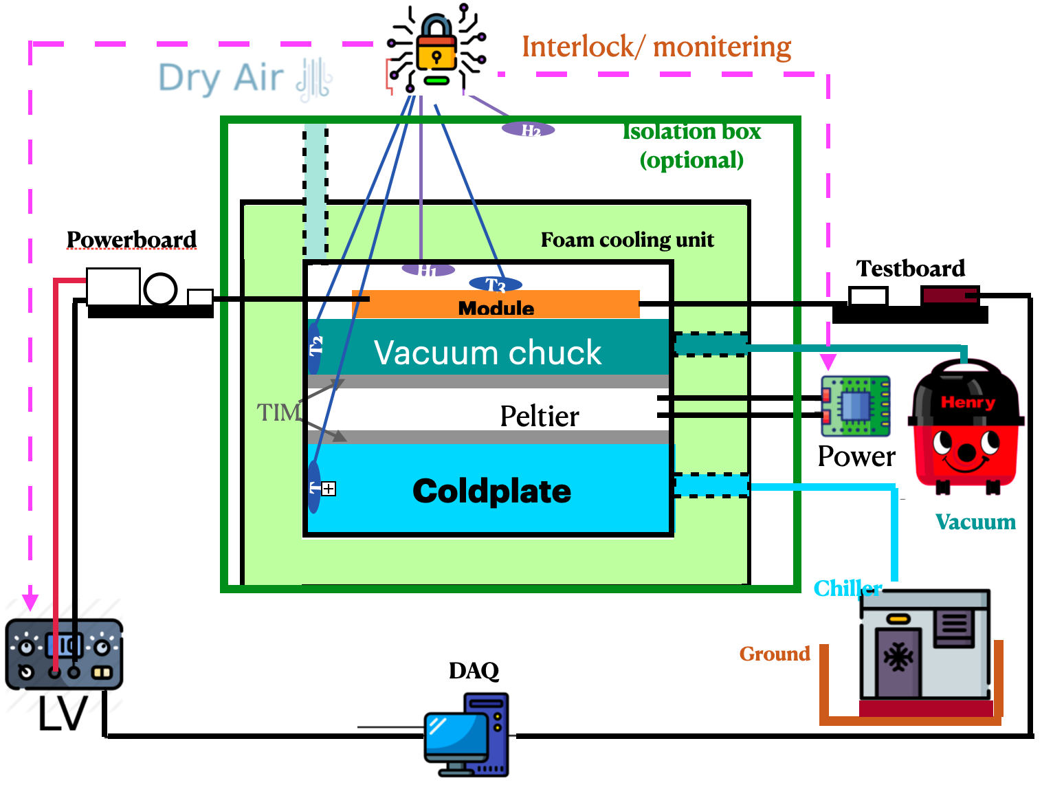
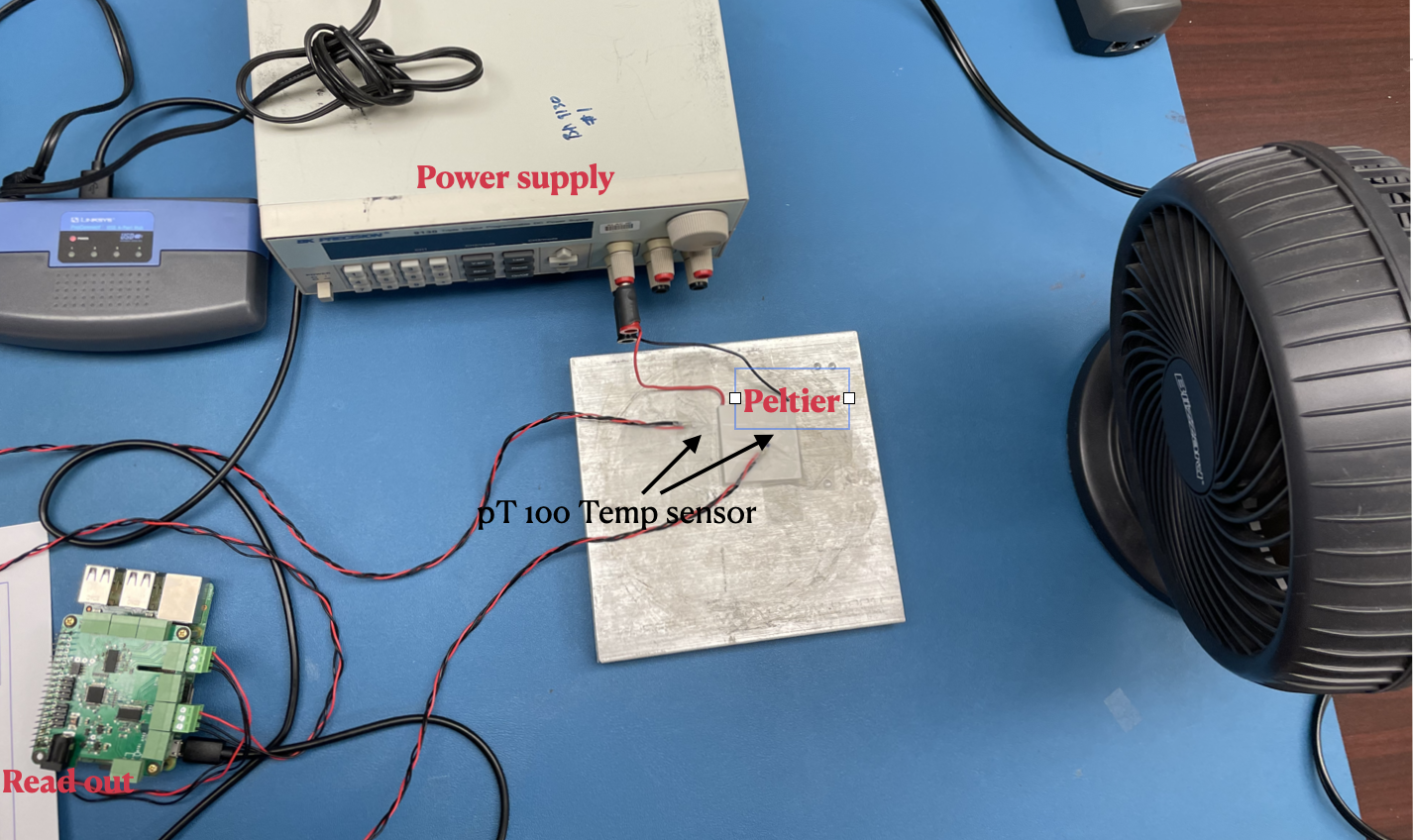
Module QC cooling test setup:
Module:
- Stage 1: test with dummy module ( now we have 6 quards and 1 singlet)
- Stage 2: test with module
Power Supply:
- Power for the peltier: bk precision power supply 9130
Cooling unit:
- Peltier: 4 sets to be tested:
- 2 layer peltier (recommend): Laird 108161050003 (53W) and Laird 387004685 (125W)
- 1 Layer peltier: Sheetak SKCM-240-11-T100-NS-TF00-ALO (75W)
- 1 Layer peltier: HP-199-1.4-0.8 (120W)
- 1 Layer peltier: HP-199-1.4-1.15 (175W)
- Chiller: ThermoCube
- Coolant: 2*700 ml link
- Dry Air
- Vacuum pump
- TIM sheet: Panasonic EYG-S0909LZX2
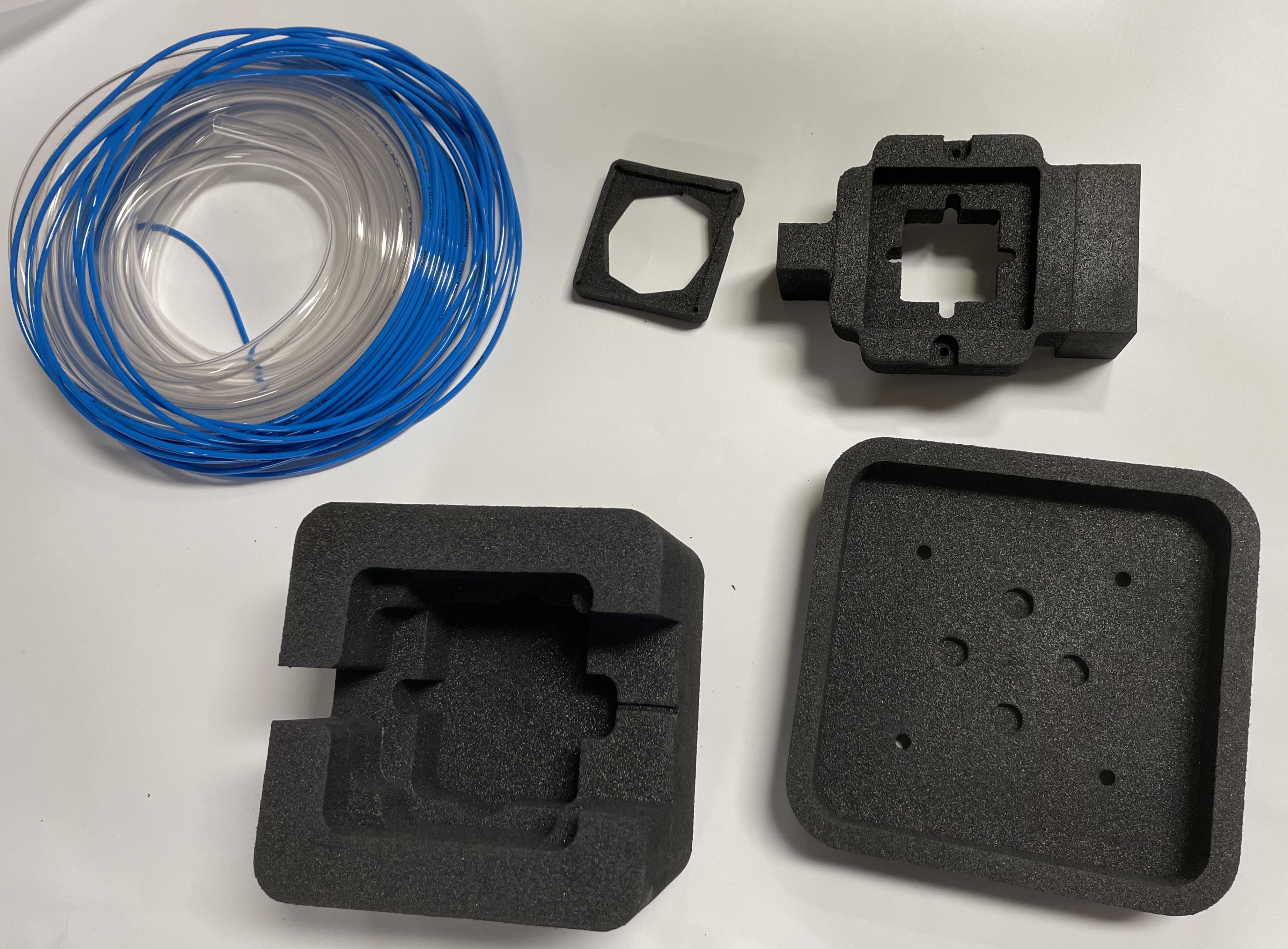
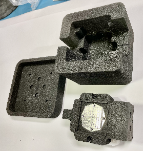
- Cooling unit foam
Monitoring unit
- Raspberry pie and RTD board
Database: link
- Sensor:
- Temperature sensor: pT100
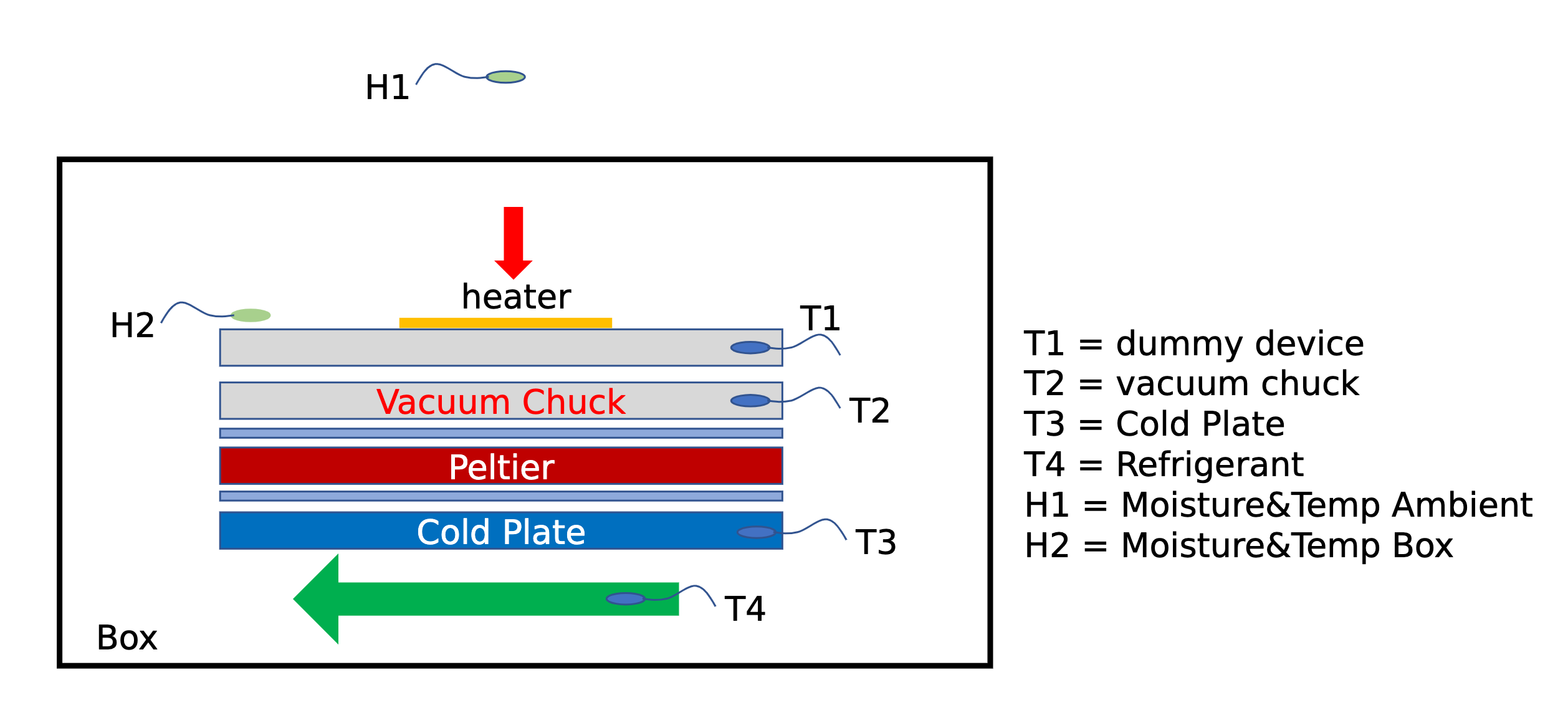
- T3: module (on the dummy module)
- T2: Vacuum chuck
- T1: Coldplate
- Humidity sensor:SHT85
- H1: Inside foam box
- H2: Inside isolation box
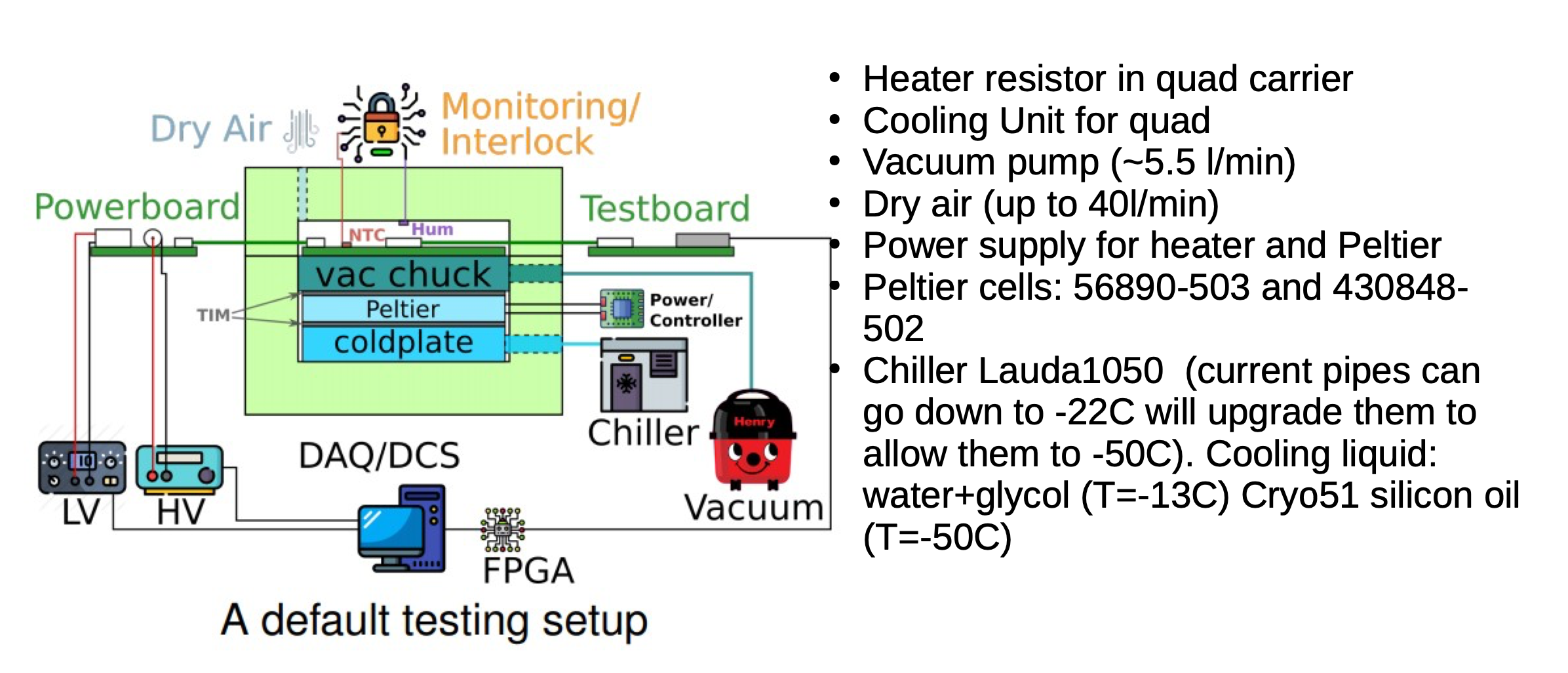
Setup from other group
The ITk pixel module cooling Twiki page is the main source for the common information. This page captures the local module cooling setup information at the SLAC Integration site. A talk by Magne Lauritzen (Jul/7/2020) has some updated status and additional pictures.
Equipment recommendation:
cooling:
- TIM: Panasonic EYG-S0909ZLX2 thermal resistance: 12.5 mK/W
- peltier:
- TEC 1 : Laird 108161050003 TEC 2 : Laird 387004685
- parallel connecting
PSU current / voltage requirement : 11 A / 8 V
- Coolant : 70% water, 30% ethylene glycol
- Coolant Temperature : -10C
- Dry air : 1.5L/min
chiller requirements: capacity > 385 W
System Test Description from Bologna : [can check this details: for Peltier and chiller need to check]
Similar settings are shown here presented by Argonne: link slide6 link2
Equipment setup:
power supply:
current / voltage: 0-10A / 0-32V
Wiener Mpod (2channel, HV/LV)
Rohde and Schwarz HMP4040
Monitoring:
Temperature: NTC
Humidity (inside cooling unit): SHT85, (+/- %RH and +/- 0.1 C)
Humidity (inside cold box): Thorlabs TSP01 (+/- accuracy)
Arduino Mega 2560
Cooling:
Cooling unit: qual cooling unit v5
Chiller: Julabo HL CF41
Coolant: 100% silicone oil
Dry, room temperature nitrogen
Room temperature vacuum
TIM sheet: Panasonic EYG-S0909LZX2
TEC combination:
TEC 1: Larid 1081611050003
TEC 2: Larid 387004685
Components :
version 1: List of components:
https://docs.google.com/spreadsheets/d/1dNT5ja_pFS2P6HJojZd5K-uXMyx7_lAjD4M-GH4URZ4/edit?usp=sharing
Apr 22 2021 List of component:
https://docs.google.com/spreadsheets/d/1BgjfFbXAt-ffoCWYGcLghxHP21pGV1TTFr1I7jS42yg/edit#gid=0
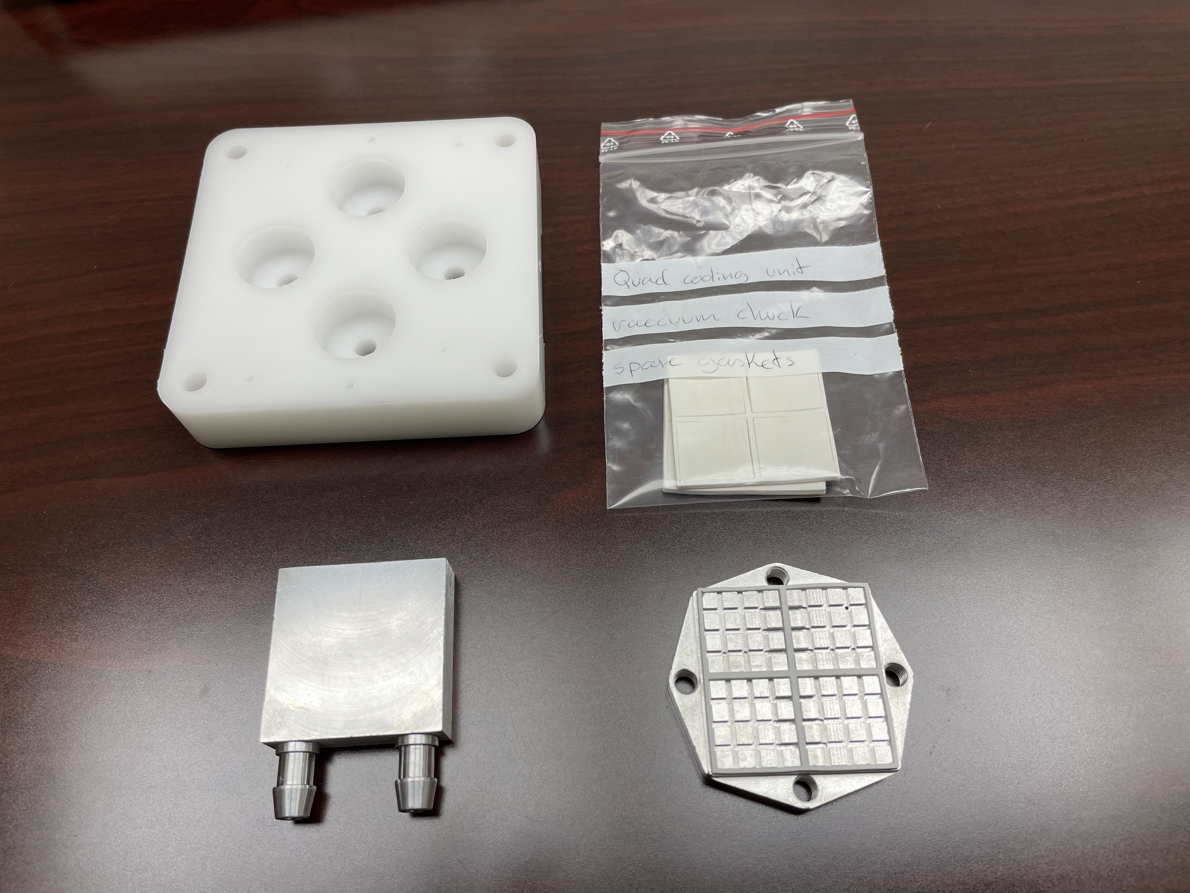
components collected f
Quad Cooling Unit Component Collection Status
Shipment from Bergen (received)
|
|
|---|
Shipment from CERN
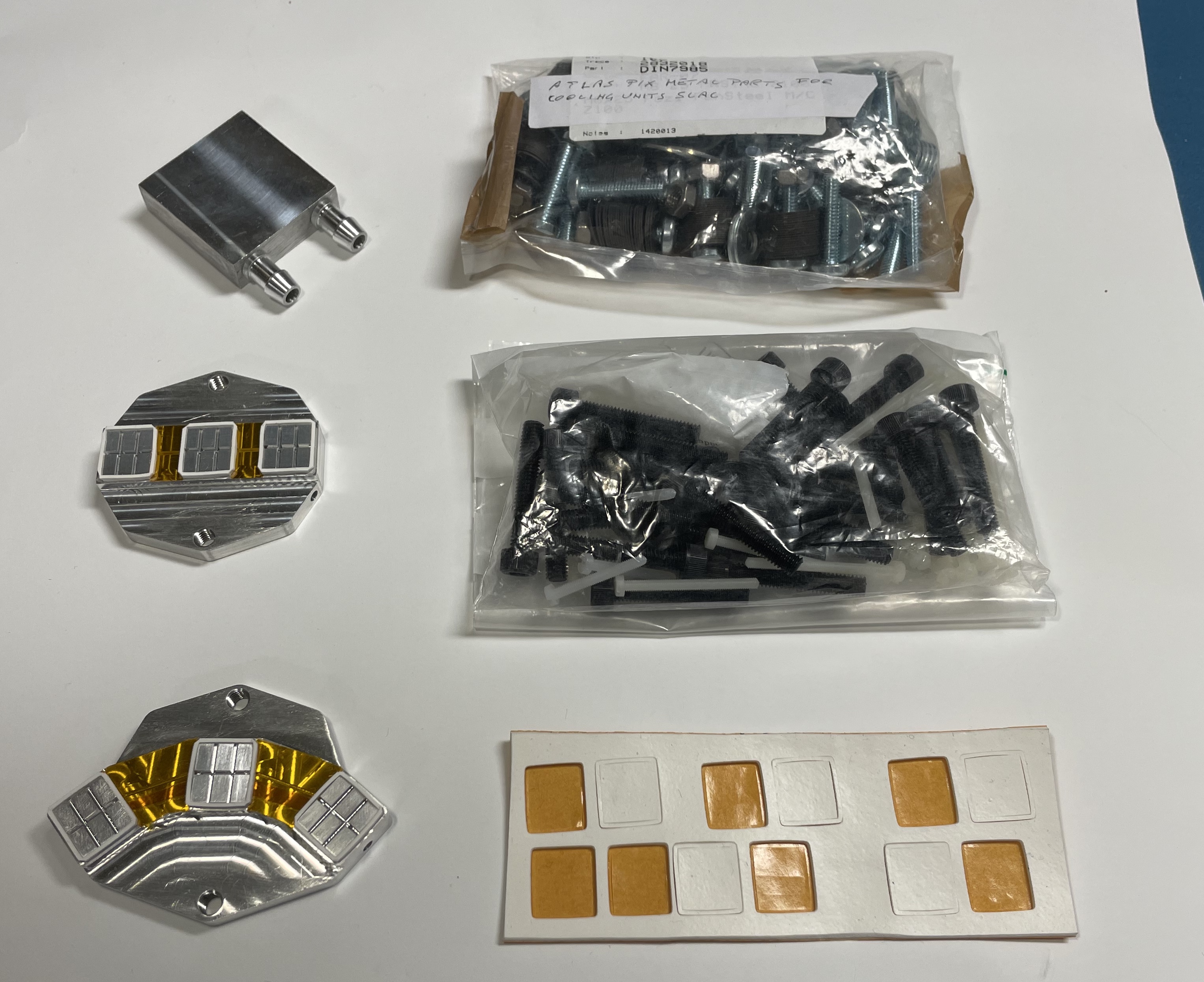
The following items are listed by names and counts from each box of the entire package from CERN. For example, there are 6 POM base plates in total, but they came as sets of there in two separate boxes. Pictures will come soon.
- Data cables for triplets RD53a ITk Pixel (x3)
- POM base plates (x3)
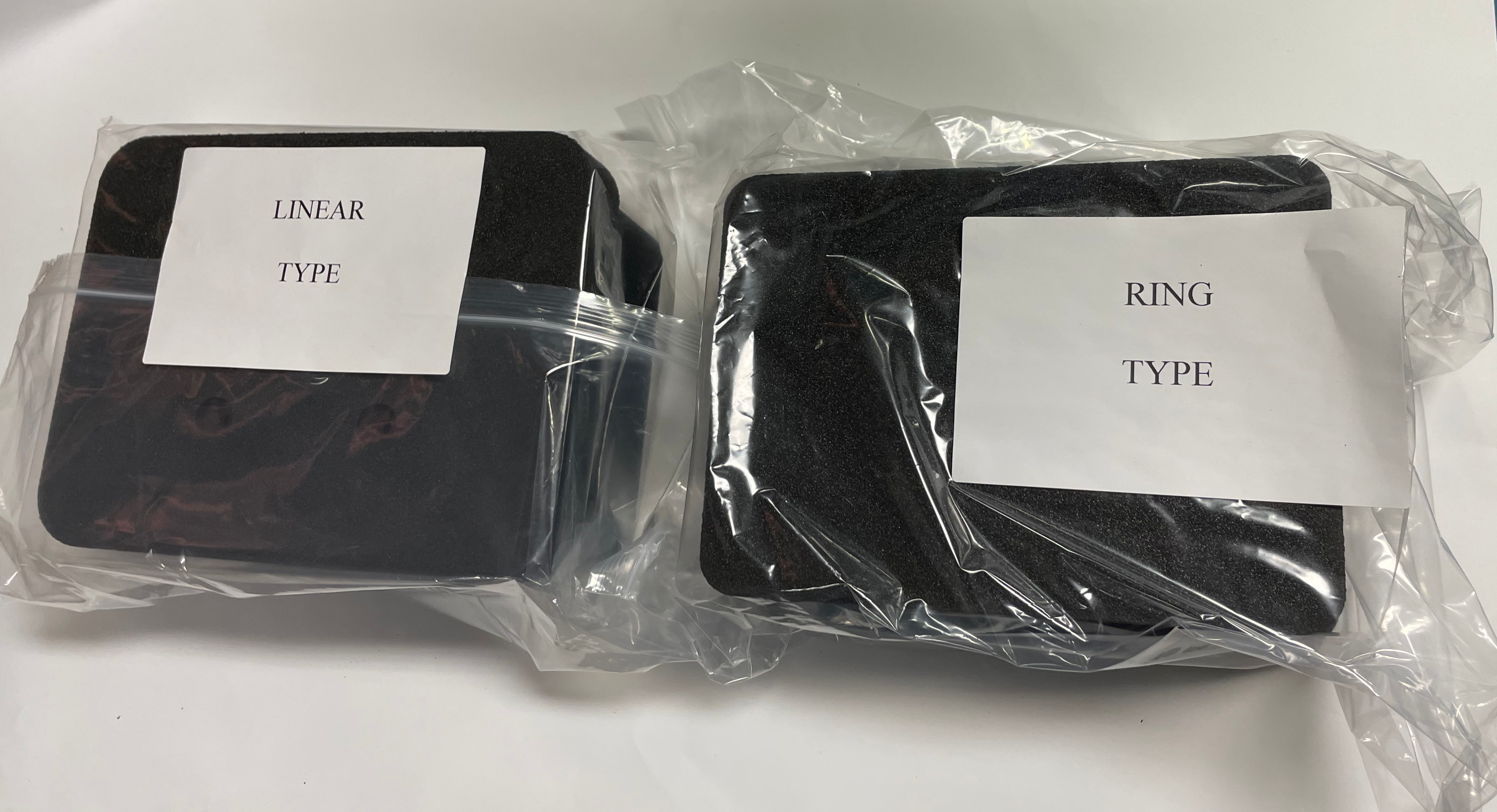
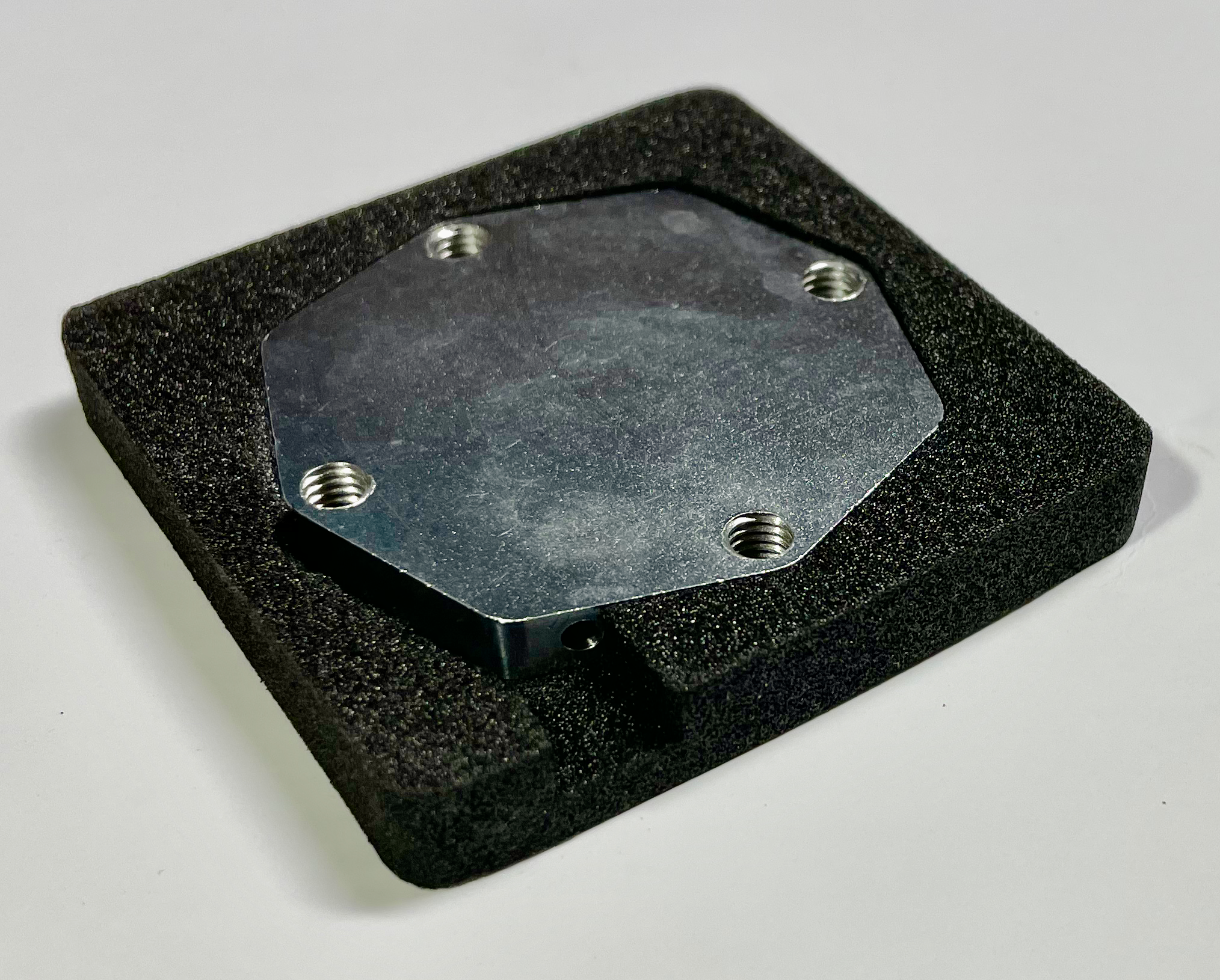
- POM base plates (x3) + coldplates for triplets "linear type" (x3) + vacuum chucks (x3)
- Triplet adapter cards RD53a ITk Pixel (x6)
- Plastic screws: RENY; NYLON M3x35, M3x25, M3x40, washers (check count for all the items) + coldplates for triplets "ring type" (x3)
- Foam insulation sets: Linear type (x3), Ring type (x3), presumably Quad V0.4 (exact type is not labeled, actual purpose to be checked) (x2)
- 25m coolant tubes
- 5m dry air / vacuum tubes
|  |  |
|---|---|---|
 |
|  |
They're being shipped from CERN 12/11 https://edh.cern.ch/Document/8559982 together with the Triplet Cooling unit.
Some notes from Saverio:
-- M6 bolt are 10/32 - we need to find more here.
-- The coolant tube is slightly shorter
-- There are spares for all the screw types and the vacuum chucks rubber pads have been already cut
Items to be acquired by INT site
- Peltier devices (see the summary of this presentation for recommendations and page 13 for the list of alternatives):
- Option 1 (tested in Bergen, 2-stage TEC): Module 1 and Module 2 (one of each per cooling unit).
- Option 2 (a single Peltier device, not yet tested): SKCM-240-11-T100-NS-TF00-ALO (Qmax 73 W) [* Q=73W is for hot side at 27 C]
- Option 3 (a single Peltier device, not yet tested): Kryotherm TB-2-(199-199)-0.8 (Qmax 95 W)
- Panasonic EYGS0909ZLX2 TIM sheets (2 sheets 4x4cm2 per cooling unit)
- Temperature sensors (NTC or PT100s, see assembly manual)
Assembly Manuals
Triplet cooling unit assembly procedure (CERN box)
Quad cooling unit assembly procedure (CERN box)
cooling unit design and technical drawing can be found here: https://twiki.cern.ch/twiki/bin/viewauth/Atlas/ItkPixCoolingUnit
Operation Instructions
E-mail from Magne Lautitzen to atlas-itk-pixel-modules-TestSystem (Oct/26/2020):
To operate the cooling unit, you will need the following infrastructure:
- Vacuum source
- Dry air or nitrogen source
- Circulating chiller
- Peltier power supply and/or controller
The amount of dry air or nitrogen needed to maintain a dry atmosphere in the cooling unit will depend on the humidity in your lab and the lowest temperature you want to reach on the module. A ballpark figure is 1.5L/min at -25C.
The circulating chiller must have a cooling capacity that depends on how cold you need to take the modules. See page 13 on this presentation for recommendations for reaching -55C.
For stable temperature control of the modules, you will need a peltier controller. I have been successfully using the Meerstetter 1089.
To avoid condensation on the peltier devices, you must maintain a dry atmosphere in the cooling unit whenever there is coolant flowing through the coldplate. If condensation forms on the peltier devices, it will degrade the performance of the cooling unit because ice and water is an excellent conductor of heat. Getting rid of this condensation requires a long term “bakeout” of the coldstack and is best avoided.
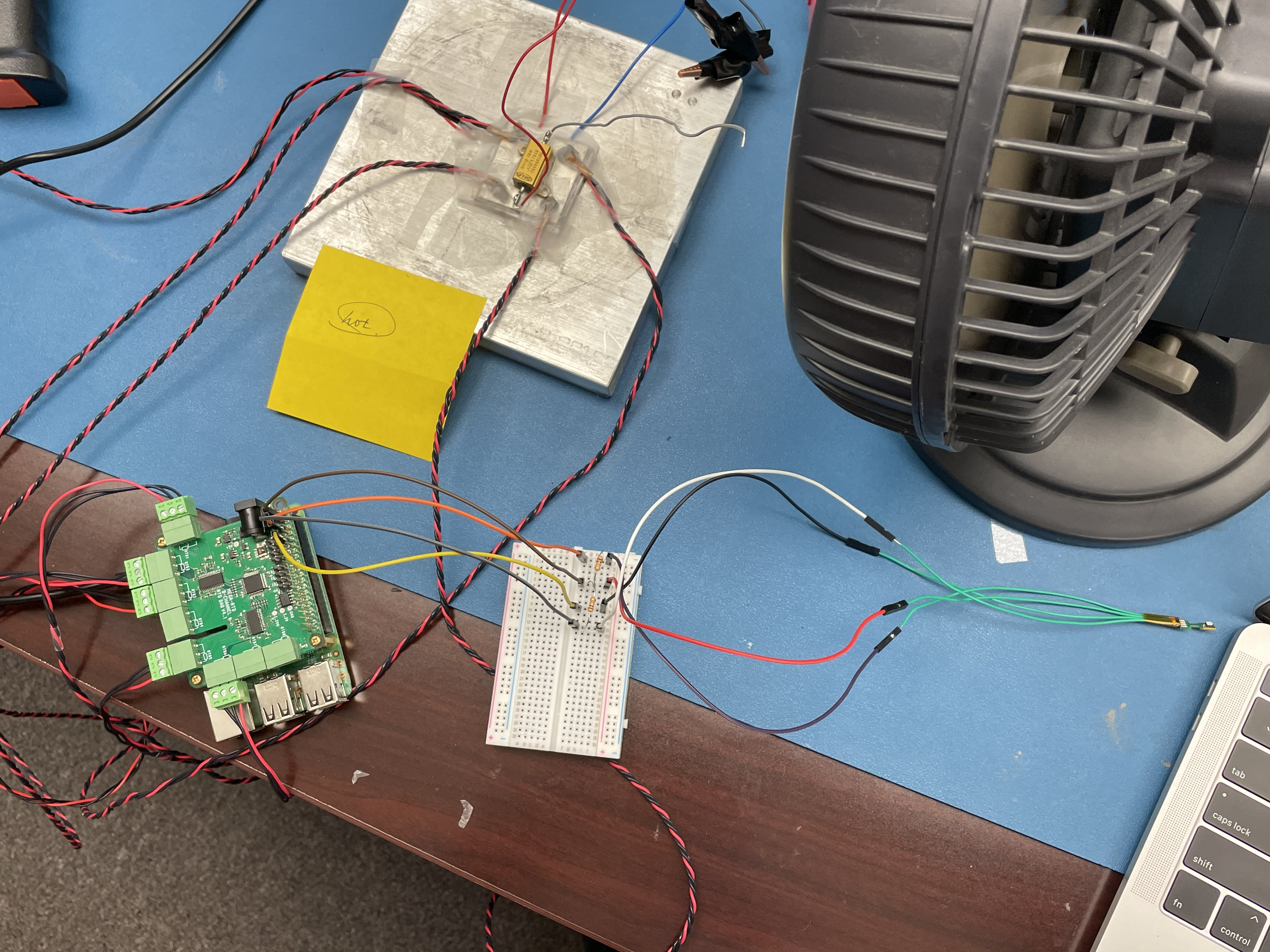
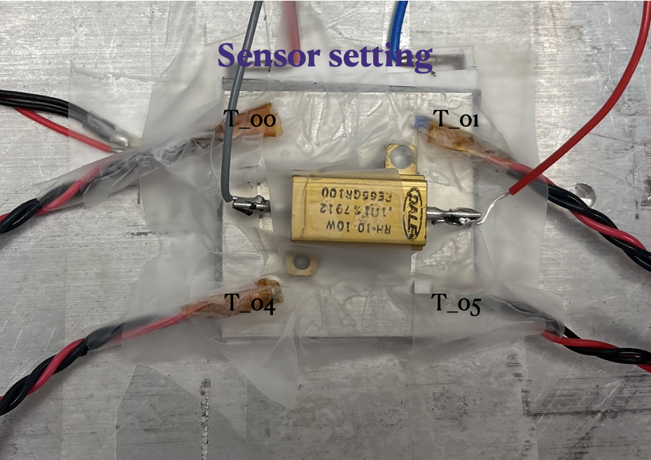
Monitoring unit and Sensor
- Monitoring setting
- 2 moisture sensor (SHT85) [sensor interface using I2C]
- 4 RTD
Temperature sensor
Temperature sensor: pT100
Humidity Sensor
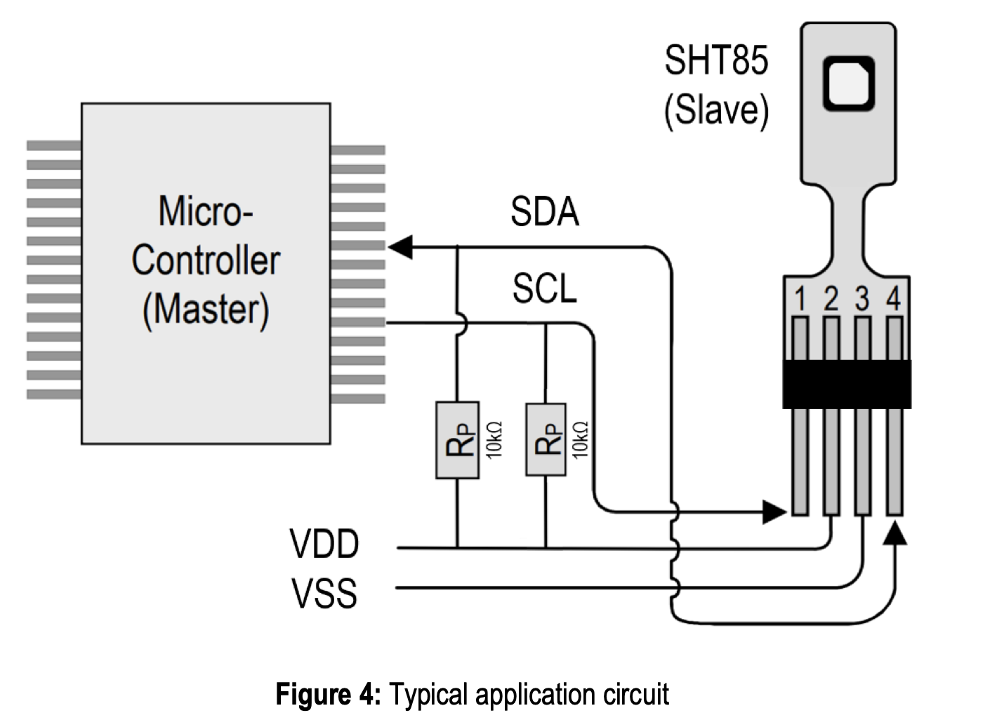
Setting up SHT85
Connecting SHT85 to raspberry pi:
Setup:
PI to SHT85 (datasheet)
pin 1 3.3V. to 2 VDD
pin 3 SDA to 4 SDA Serial data
pin 5 SCL to 1 SCL Serial clock
pin 9: ground to 3 VSS Ground
Testing for sensor: Reading ( Temp(C), Humidity (%), Dew Point (C))
Monitoring
Readout: RTD Data Acquisition Stackable Card for Raspberry Pi with Raspberry Pi
Firmware to control: https://github.com/SequentMicrosystems/rtd-rpi
For SHT85: https://github.com/jothanna/sht85/tree/master/sht85
connecting to the raspberry pi:
- connecting to the rddev111
- ssh pi@192.168.4.122
- password: slac-dcs-cooling
Readout RTD database:http://atlascr.slac.stanford.edu:3000/d/AhqDEQ_Mk/dcs-cooling-tests?orgId=1&from=1619033502000&to=now&refresh=1m
(login atlas/atlas)
Interlock
Cooling unit interlock:
conditions and action:module too cold: T (module) < -45 C and T(coldplate) > -45 C : turn off peltier and turn off module + chiller
module too hot: T (module)> 35 C : turn off module and peltier (?) + chiller
condensation:
T (module) < dew points: turn off peltier and turn off module + chiller
flow of dry air < 1.5 L/min (? number need to be tested): check dry air connection
vacuum status: alarm
pressure gauge (threshold) : check vacuum status or piping
T(module)-T(vacuum chuck)>threshold (need to test if the module and vacuum chuck not connect well what is the number) : check vacuum status or piping
peltier properly setup:
T(vacuum chuck) > T(chiller): turn off module and peltier
chiller status: alarm
(need to consider about leakage of coolant or some problem related to chiller) T (coldplate) -T(chiller set) > threshold (need to check) => need to shut down pelter + module + chiller
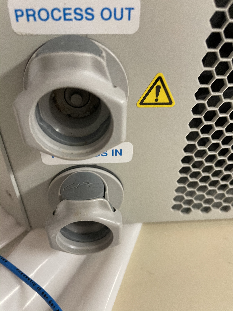
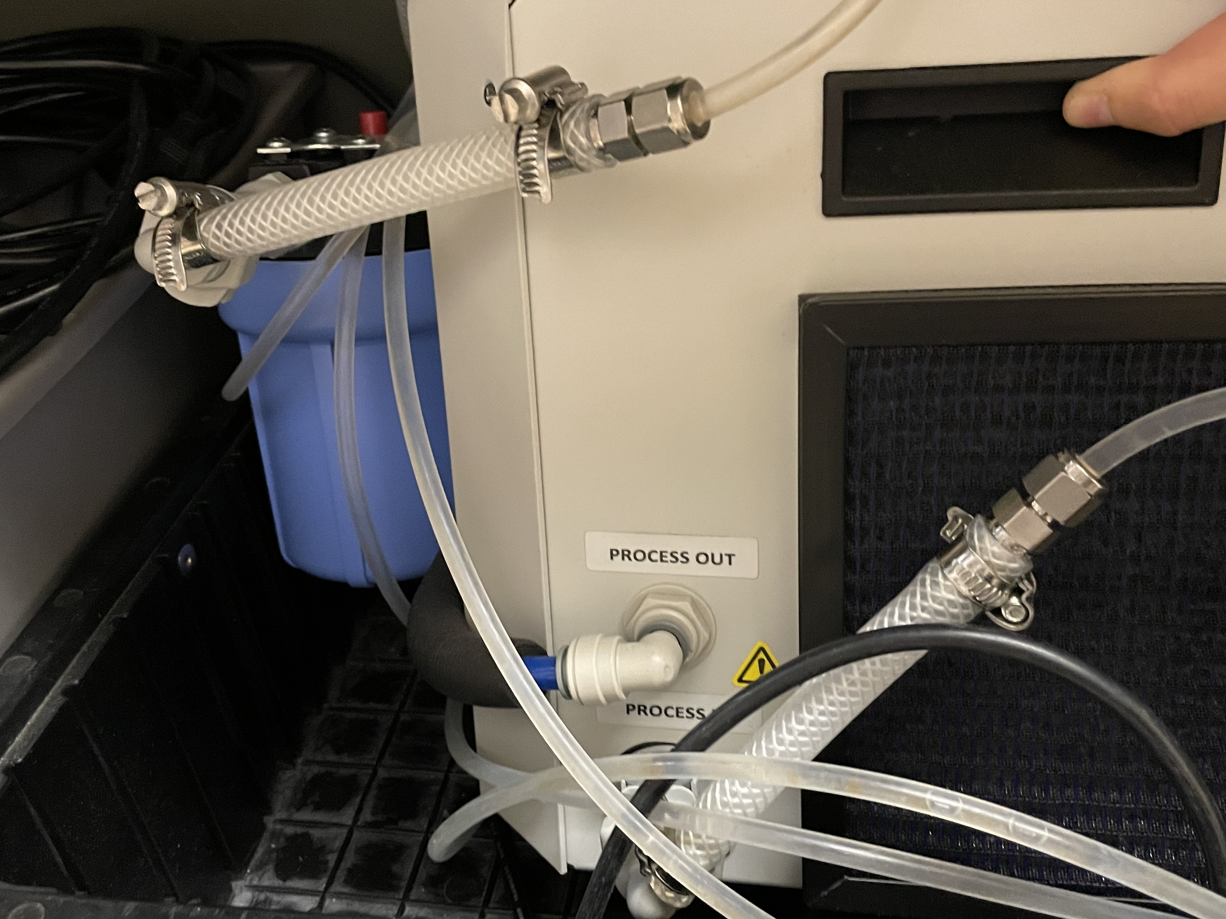
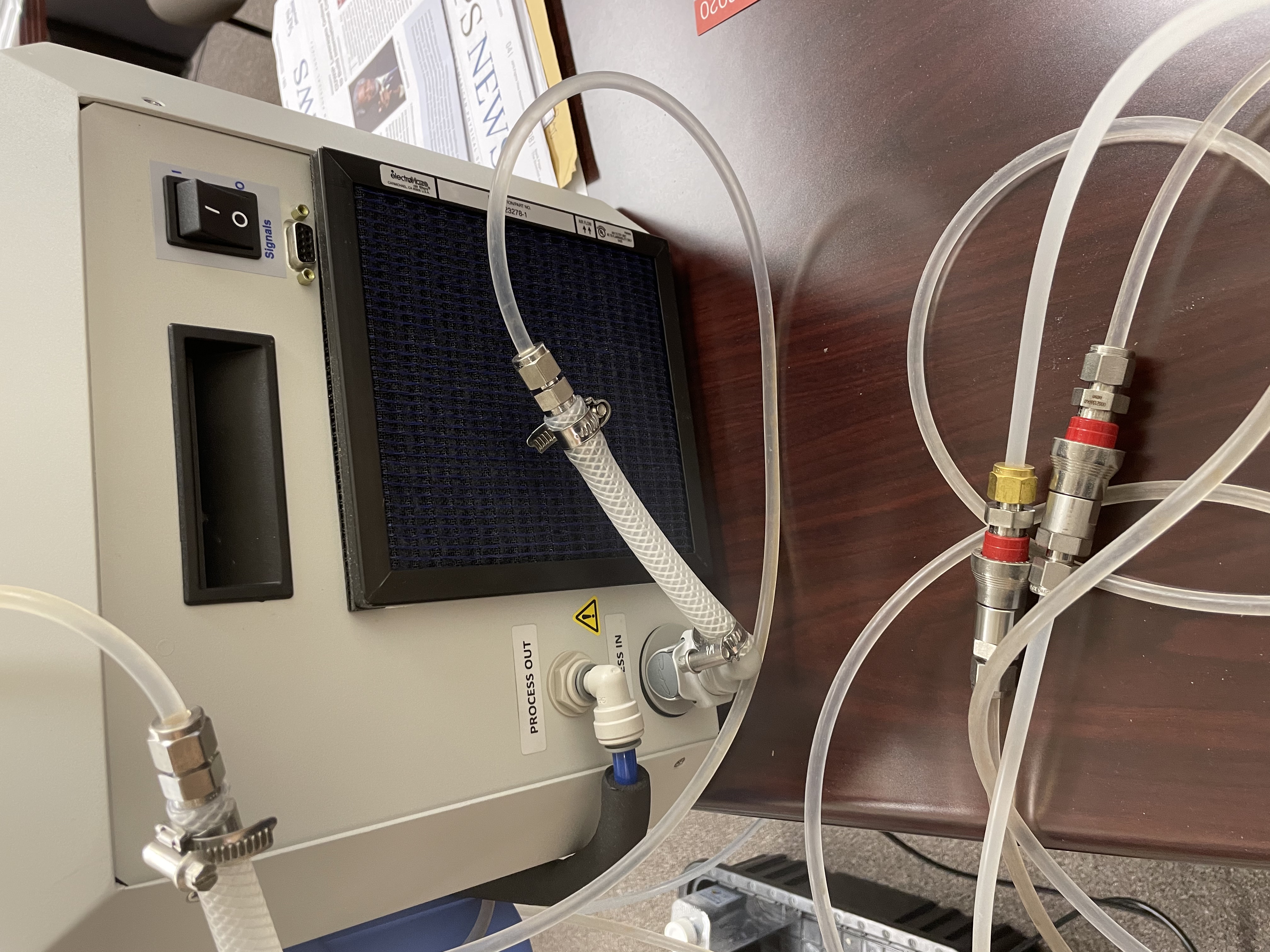
Chiller
There are two ThermoCube units in B84/TID cabinet. Unit #1 is with full tubing setup and regularly used by Gabriel Blaj for LCLS so that we are trying to use unit #2 (no tubing) by assembling similar tubing arrangement as unit #1. Unit #2 has different coolant connectors compared to unit #1, but the rest of the tubing can work the same way still.
| Unit #2 Model | 10-400-3G20-1-CP2-R2-LT-AR |
|---|---|
| -400 | ~400W @ 20C with ambient air cooling for the Cube |
| 3G20 | >3 lpm @30 pig magnetic drive gear pump. Adjustable flow setting for 2 lpm. |
| CP2 | 3/8" CPC shut off valve (1-3 lpm) |
| R2 | RS232 interface controller |
| LT | Low temperature operation (<5C) |
| AR | Auto reset - software |
* product details: https://www.sscooling.com/product/thermocube-liquid-to-liquid/
*manual: https://www.sscooling.com/wp-content/uploads/2021/07/ThermoCube-Liq-Liq-Manual-Rev-M13.pdf
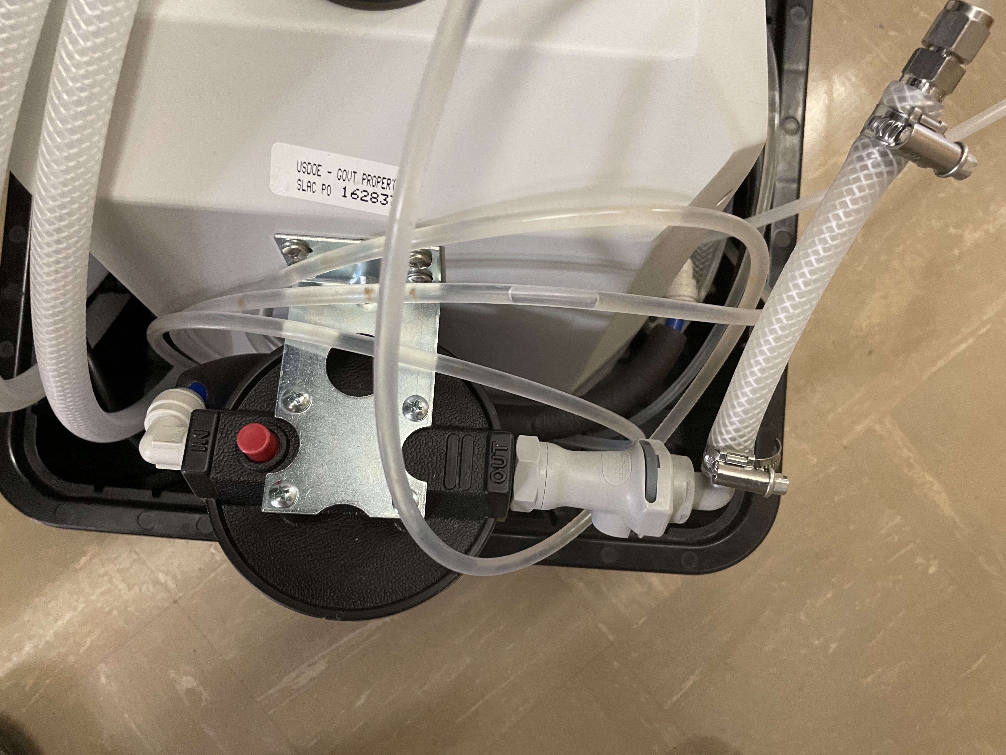
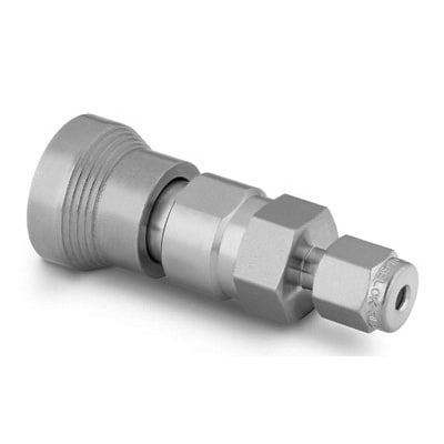
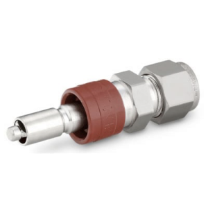
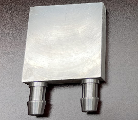
| Coolant connector (3/8" CPC) on unit #2 | Connection to the filter for unit #1 | Unit #1 with Swagelock QC4-316 joint for application insertion | Unit #1 view from above its filter |
|---|---|---|---|
| |
|
|
Thermo Cube: Chiller manual
Tubing
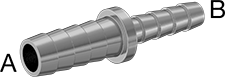
- A) Application section (2*140cm): Our application tubing came with the CERN shipment is a Saint Gobain Tygon S3 E3603 NSF-51 with 8mm ID/11.5mm OD that fit well onto the cooling block barb (ridge ID/OD=0.306"/0.363"=7.8/9.2mm). To avoid adapting metric-Imperial tubing, we also tried a 1/4" soft tubing and that seemed to just about being able to get on the cooling block barb with very tight fit. Since we may never dissemble the cooling block after initial assembly, we opted to go with the 1/4" ID and 3/8" OD tubing so that the two ends can fit onto the Swagelok Instrumentation quick connect QC6-316 (SS-QC6-D-600 / SS-QC6-B-600) with 3/8" fitting. Aiming for the same soft PVC Tygon chemical tubing as the original CERN part with ID/OD=1/4"/3/8" corresponds to McMaster-Carr #5155T26. Do we need a shut off valve near module to allow faster warmup ?
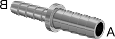
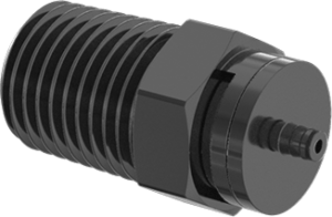
- B) Application joint to chiller Process In (30+15cm): Application joint is QC6-316 ( SS-QC6-D-600 / SS-QC6-B-600 ) as for A) with 3/8" OD tube ( McMaster-Carr #5155T26) for ~30cm then transition (with McMaster-Carr #91355K32) to a short (~15cm) 3/8" ID tube (McMaster-Carr #5155T34) to fit onto the 3/8" hose barb from the HFC 12 series (rating only down to 0C ?) which can connect with the 3/8" CPC at chiller Process In.
- C) Application joint to filter (or Process Out) (30+15cm): similar piece like B), such that the hose barb end can plug directly into the chiller Process Out, or filter out.
- D) Filter: The nominal filter appeared in ThermoCube's manual is with the Pentair/Pentek polypropylene housing (Grainger #1ECR5) which has 3/8 NPT female interface. Other auxiliary components also can be found at Grainger: Mounting bracket, wrench. ThermoCube recommended filter cartridges are the 5 micron particle filter which can be Pentair/Pentek filter cartridge (Grainger #3FRU1). Also needs caution whether filter is compatible with <0C coolant. The filter output end should be fitted with the 3/8" NPT shutoff as those on the chiller unit. The short section from filter inlet to chiller Process out doesn't need disconnecting at the filter housing after the initial installation so can just take a fixed 3/8" MNPT to 3/8" barb fitting to transition to 1/2" tube over the 3/8" hose barb to connect to the chiller Process Out.
- E) Jacket insulation: We need to insulate all sections of tubing with foam jacket to allow running coolant <~0C. It may be simplest to use a long continuous slitted piece runs over everything. A 7/8" ID and 1/2" thickness slitted tube is envisaged and the ID is mainly constrained bu the hose clamp profile.
Tables for chiller cycle tubing connection:
| c) From process out (chiller) to filter | ||||
Coolant connector (3/8" CPC) on unit #2 (PROCESS OUT) | 3/8" Hose Barb HFC 12 Series Polypropylene Elbow Coupling Insert - Shutoff: link | 3/8" ID 1/2" OD tube (E-3603 Tygon PVC Tubing for Chemicals ) link45 cm (?) | 3/8" MNPT x 3/8" Hose Barb Polypropylene ElbowLink | 3/8" NPT female interface of filter housing link |
|---|---|---|---|---|
|
|
|
| |


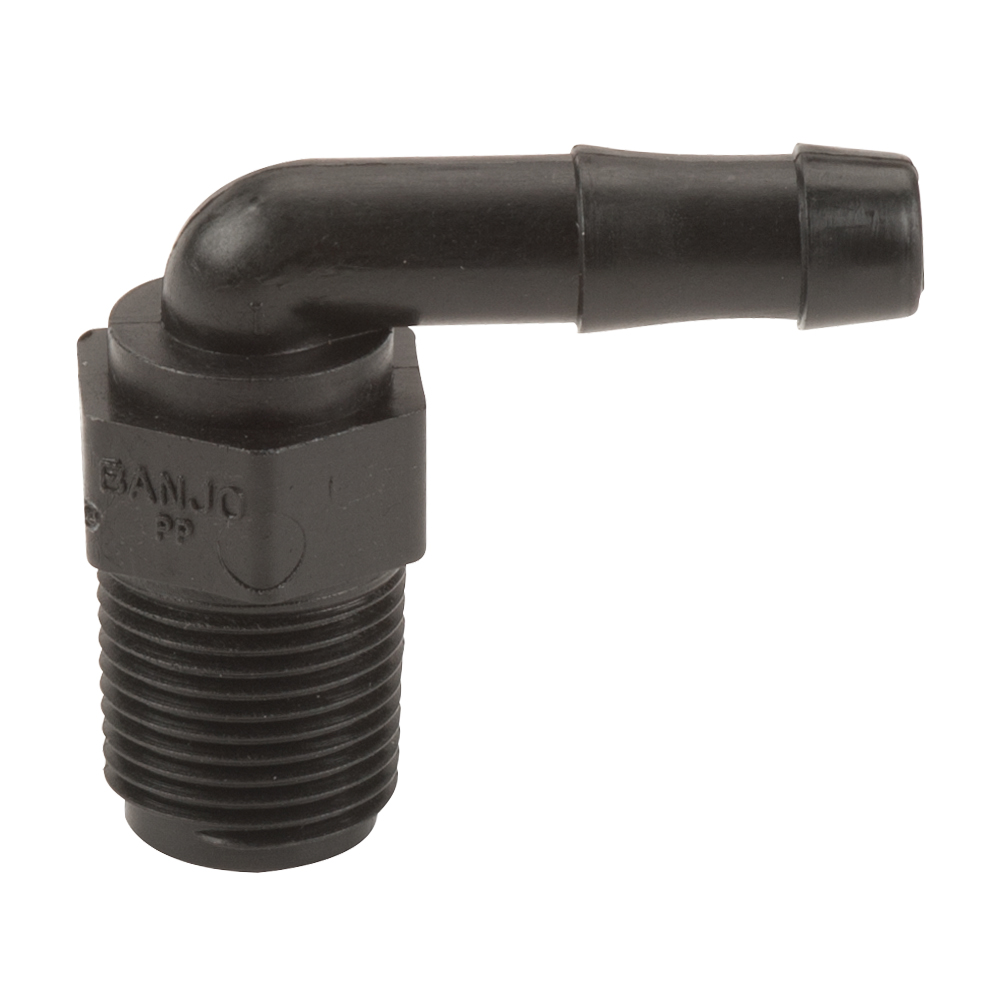
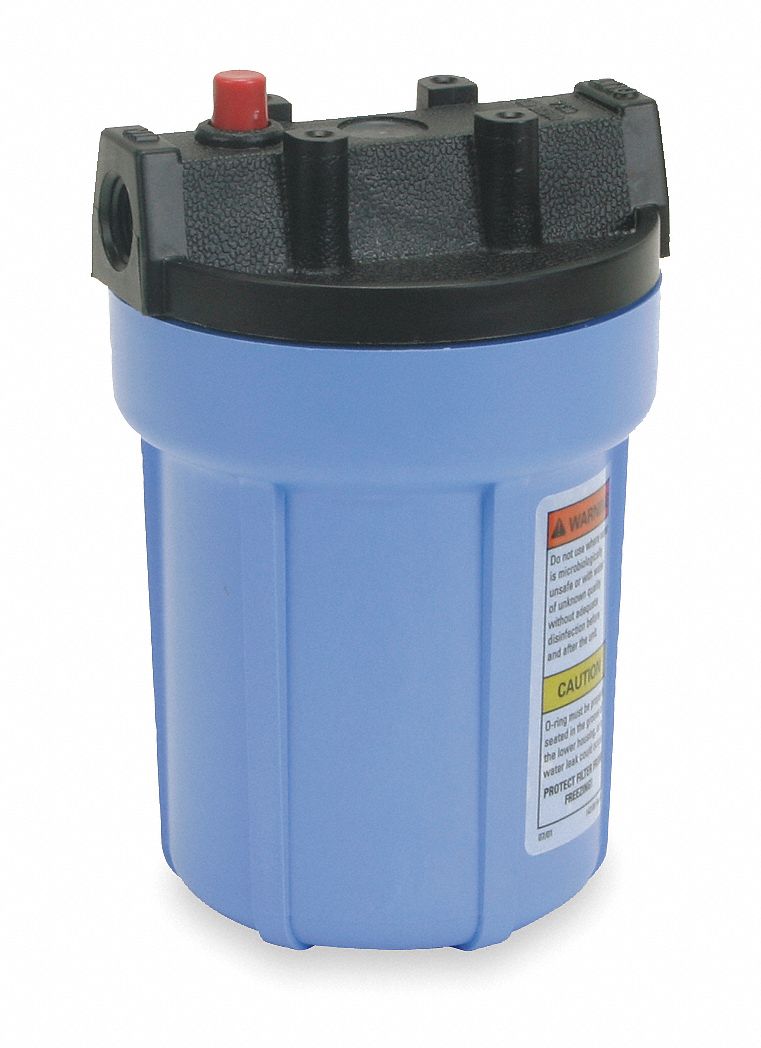
| From filter(out) to application (cold plate) | |||||||||
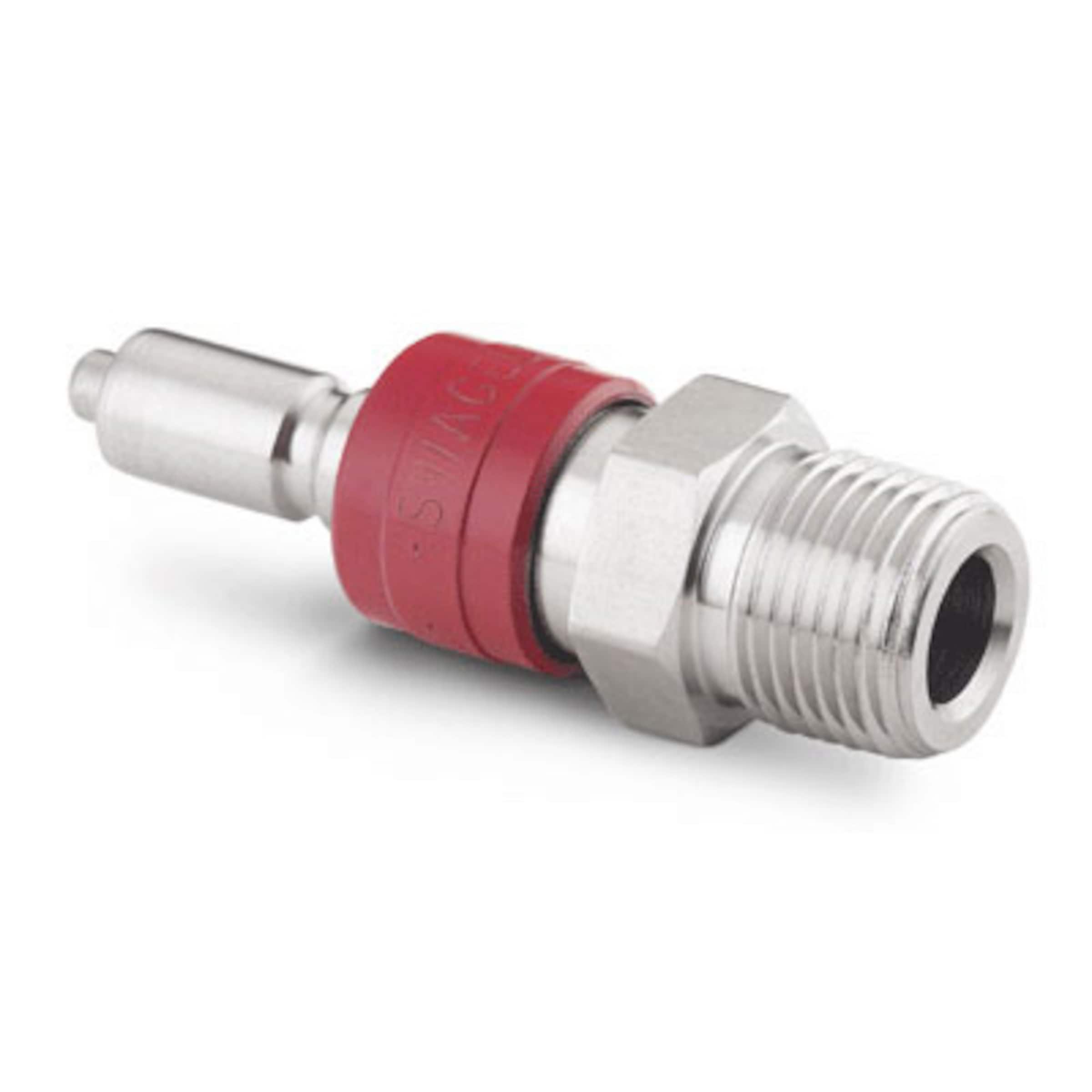
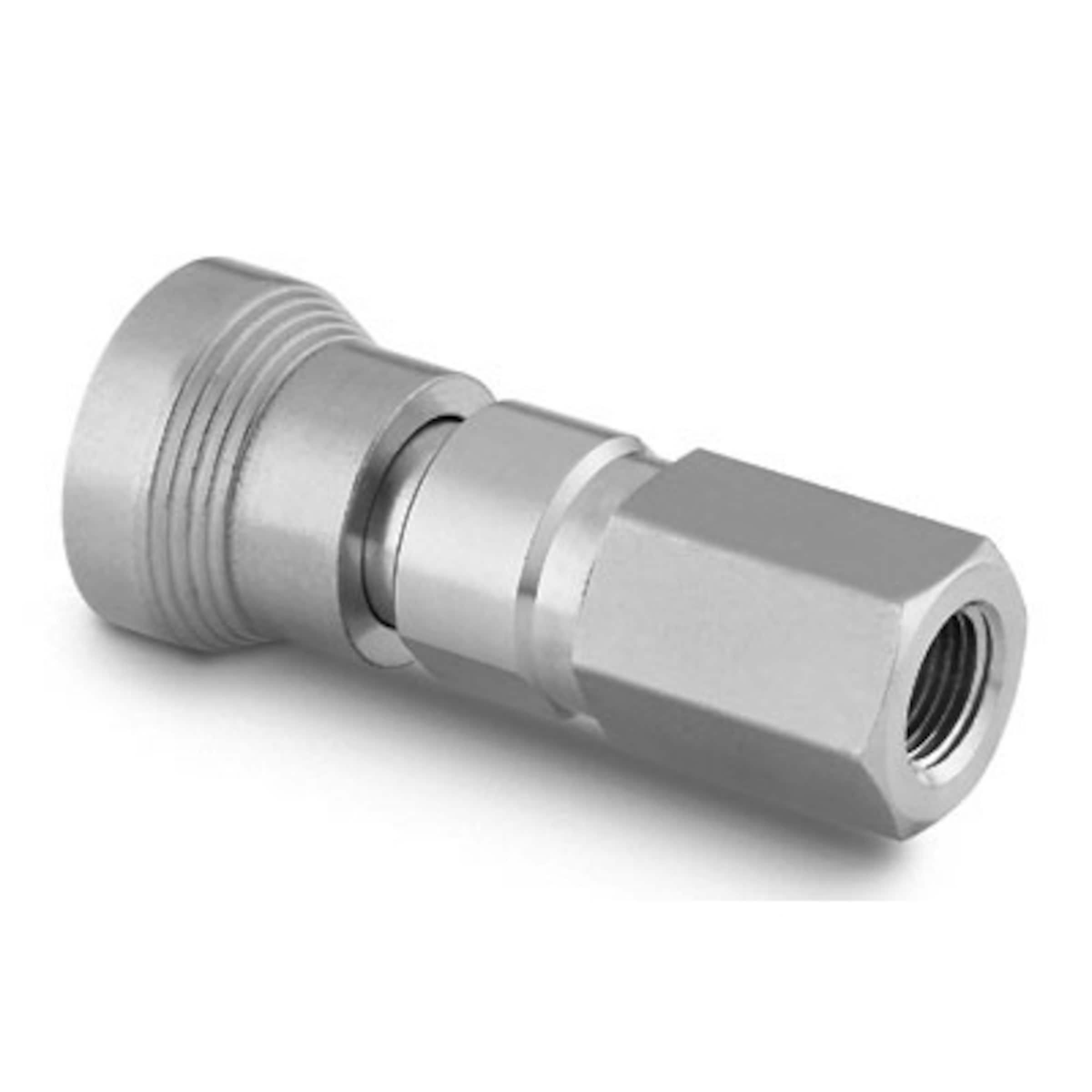
3/8" NPT female interface filter housingLink | 3/8" NPT HFC 12 Series Polypropylene Coupling Body - ShutoffLink | 3/8" Hose Barb HFC 12 Series Polypropylene Elbow Coupling Insert - Shutoff:Link | 3/8" ID 1/2"OD tube(E-3603 Tygon PVC Tubing for Chemicals ) 15 cm | Brass Barbed Hose Fitting for Air and Water(Straight Reducer for 3/8" x 1/4" Hose ID )Link | 1/4" ID and 3/8" OD ( E-3603 Tygon PVC Tubing for Chemicals)Link30 cm | Swagelok Instrumentation quick connect ( Stainless Steel Instrumentation Quick Connect Body ) SS-QC6-B-600 (3/8") | Swagelok Instrumentation quick connect ( Stainless Steel Instrumentation Quick Connect Stem with Valve ) SS-QC6-D-600 (3/8") | 1/4" ID and 3/8" OD ( E-3603 Tygon PVC Tubing for Chemicals) 140 cm | cold plate (can fit 1/4 " ID) |
|---|---|---|---|---|---|---|---|---|---|
|
|
|
|
|
|
|
|
| |

| From application (cold plate) to chiller (process in) | |||||||||
| cold plate (can fit 1/4 " ID) | 1/4" ID and 3/8" OD ( E-3603 Tygon PVC Tubing for Chemicals) 140 cm | Swagelok Instrumentation quick connect ( Stainless Steel Instrumentation Quick Connect Body ) SS-QC6-B-600 (3/8") | Swagelok Instrumentation quick connect ( Stainless Steel Instrumentation Quick Connect Stem with Valve ) SS-QC6-D-600 (3/8") | 1/4" ID and 3/8" OD( E-3603 Tygon PVC Tubing for Chemicals)Link30 cm | Brass Barbed Hose Fitting for Air and Water(Straight Reducer for 3/8" x 1/4" Hose ID )Link | 3/8" ID 1/2"OD tube(E-3603 Tygon PVC Tubing for Chemicals)Link15 cm | 3/8" Hose Barb HFC 12 Series Polypropylene Elbow Coupling Insert - Shutoff:Link | 3/4" NPT HFC 12 Series Polypropylene Coupling Body - ShutoffLink | Coolant connector (3/8" CPC) on unit #2 (PROCESS in) |
|---|---|---|---|---|---|---|---|---|---|
|
|
|
|
|
|
|
|
| |
Coolant
We intend to use the ThermoCube recommended coolant Koolance 702 (27% propylene glyco + water mix): https://koolance.com/liq-702-liquid-coolant-bottle-high-performance-700ml-blue. Propylene glyco is a nicer substance (used as food additive in some cases) than the more commonly used ethylene glyco as an alternative antifreeze.
The ThermoCube tank is 300 ml but there may be some additional piping volume within chiller besides the 300ml. The tubing outside the chiller (not including filter) is <~200ml. So it may sufficiently safe if we get two 700ml bottles of the recommended Koolance 702. This unit description doesn’t say what type of cold plate it has. Stainless would have carried a tag ’S” in the model number somewhere so this may be old style anodized AL PCW plate ? Koolance claims to be friendly with both Al and SS.
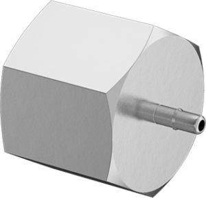
Vacuum Pump
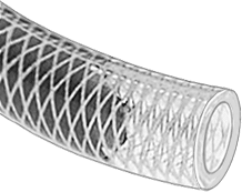
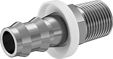
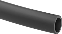
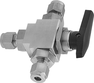
The vacuum chuck has 3mm diameter hole for the vacuum line tube (OD/ID=3mm/1.8mm). The vacuum pump at B84 EPP lab is a GAST DOA-P704-AA with max pressure of 4 bar (60 psi). The left port (looking from front) has a 3/8" barb that we intend to connect a braided firm polyurethane rubber tube (McMaster-Carr #51165K12) with ID:OD=3/8":5/8" which runs ~1.5m from below the table to the top of table. This pump vacuum tube then transitions to the short (~30cm) 3mm OD vacuum chuck tube with a shut off valve and vacuum gauge in the transition region so that vacuum on the cooling unit can be held with monitoring after pumping. Since the vacuum gauge connection are mostly SS, we also opt for SS parts: Push on hose fitting (McMaster-Carr #53515K31) with 3/8" barb for pump tube transition to 1/4" NPT followed by On/off valve (McMaster-Carr #45395K216) and 1/4" Tee (McMaster-Carr #4452K432) for vacuum gauge mount. The Tee port is compatible with the Omega OEM pressure transmitter PX119-015AI, with SS 1/4" NPT mount and a 0-15psi absolute pressure measurement range. This device with miniDIN 43650C connection can be read out by the WidgetLords Pi-SPi-8AI Raspberry Pi Analog Input Interface (the originally favored Sequent Industrial Automation Raspberry Pi interface card was sold out). The final connection to the vacuum chuck tube could use a nylon part with 1/16" barb and 1/4" NPT (McMaster-Carr #5153K37). Unfortunately here is no SS bodied corresponding part. The 1/16" (1.59mm) barb is a approx match to the vacuum chuck tube with ~1.8mm ID (adequate tightness to be verified).
| GAST DOS-P704-AA | Left pump port with 3/8" barb |
|---|---|
|
|
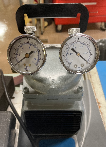
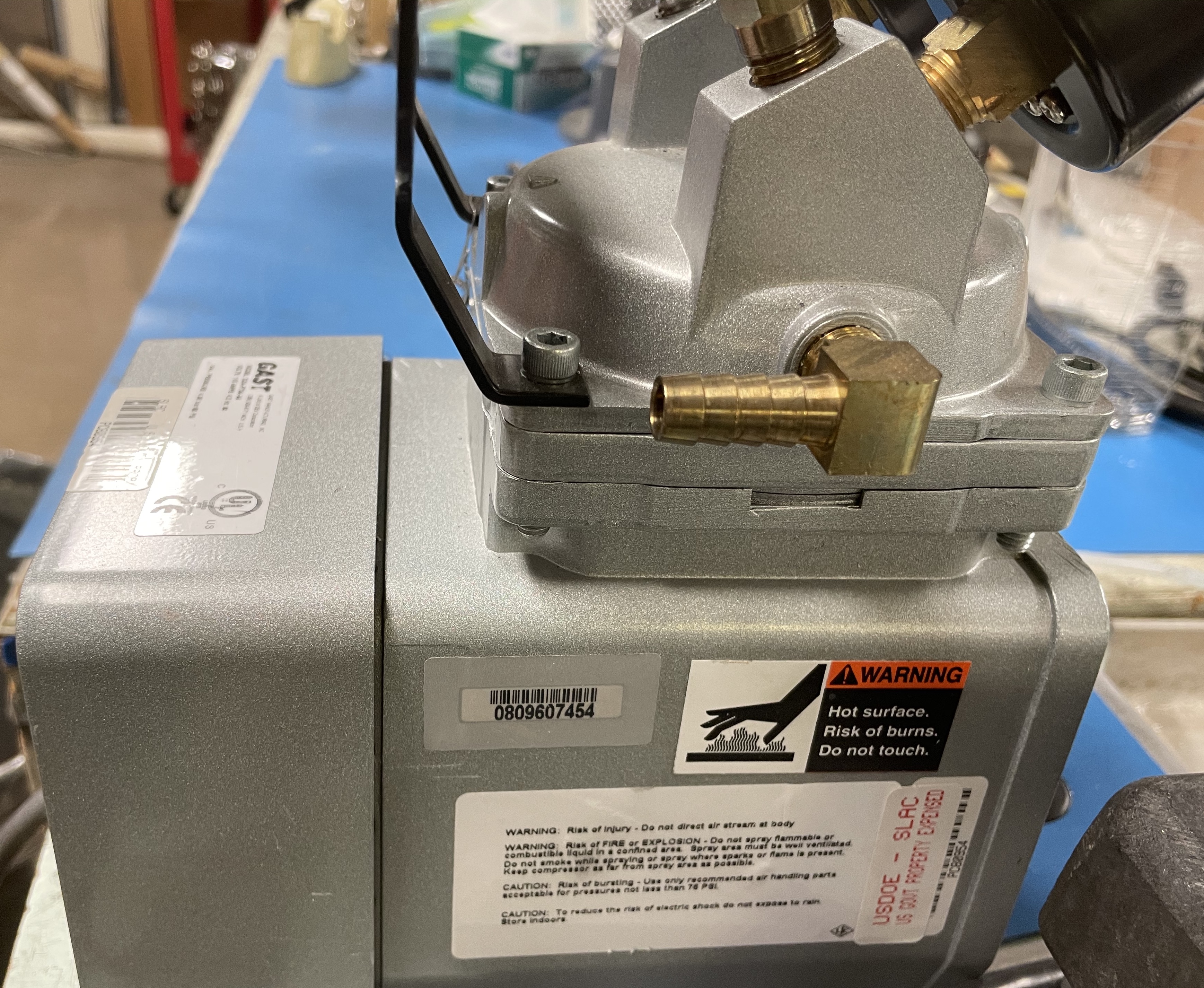
Table for vacuum unit connections
| Left pump port with 3/8" barb | High-Pressure Firm Polyurethane Rubber TubingID:OD=3/8":5/8" Link ~1.5 m | 316 Stainless Steel Push-on Hose Fitting for Air and Water3/8" Hose ID, 1/4 NPT Male End Link | On/off valve High-Pressure Compact 316 Stainless Steel On/Off Valvewith lock-able T-handle, 1/4 NPT Female x 1/4 NPT Male | 1/4" Tee316 Stainless Steel Threaded Pipe FittingLow-Pressure, Tee Connector, 1/4 NPT Female | Stainless Steel Instrumentation Quick Connect Stem with Valve, 0.2 Cv, 1/4 in. Male NPT SS-QC4-D-4PM | Stainless Steel Instrumentation Quick Connect Body, 0.2 Cv, 1/4 in. Female NPT SS-QC4-B-4PF | Plastic Barbed Tube Fitting for Air and WaterSwivel Adapter, for 1/16" Tube ID (1.6 mm)x 1/4 NPT Male | cern tube OD/ID=3mm/1.8mm (~30cm) |
|---|---|---|---|---|---|---|---|---|
|
|
| (replacing original unavailable part) |
|
|
|  |

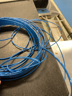
Dry Air
| The dry air filters were saved by Matt from BaBar, residing inside the curtained area of B84 EPP lab. House compressed air are filtered to let out through the flow meter with a max flow of 20 ft3/min. A 80ft long hard polypropylene tubing with 1/4" OD (McMaster-Carr #9349T2) takes the drive air down to the ATLAS benches. The dry air supply tube terminates at a diverting valve (no shutoff) (McMaster #45165K42) on the bench to allow the switching of the dry air between a test port and the through path to module cooling unit. The through path continues with the same type of tube to transition to the 30cm long dry air tube into the module cooling unit which is an ID/OD=1.8mm/3.0mm blue tube from CERN shipment (same as the vacuum tube). This transition uses a pair of Aluminum low-pressure 1/4 NPT adaptor to barbed tube fitting: 1/4" barb - male NPT (with O-ring) on supply side (McMaster-Carr #5058K441); 1/16" barb and female NPT on module side (McMaster-Carr #5058K641). The initial turn on of dry air should let run for a few hours with the outlet going to the test port using the diverting valve. Check flow and humidity at the test port before flowing into the module cooling unit. Once on for operation, the dry air flow should not be turned off. From an off state, the restart should always have the few hours of initial flush first. During operations, if the dry air needs to be off at the module cooling unit, use the diverting valve to temporarily directing the air to the test port. |
|---|
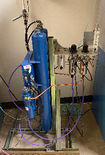
table for dry air connection
long hard polypropylene tubing with 1/4" OD11/64" ID, 1/4" OD~ 80 ft | Diverting Valve with Yor-Lok Fittingsfor 1/4" Tube OD, 316 Stainless Steel BodyLink | Aluminum Low-Pressure Barbed Tube Fittingfor Air and Water, Adapter for 1/4" Tube IDx 1/4 NPT Male | Aluminum Low-Pressure Barbed Tube Fittingfor Air and Water, Adapter for 1/16"(1.6mm) ID Tube x 1/4 NPT Female | cern tubeOD/ID=3mm/1.8mm(~30cm) |
|---|---|---|---|---|
|
one to application/ one to testing area |
This part is not quite right - should be 1/4" OD. Should have looked harder for ideally a single part with Yor-lok for 1/4" OD tube at this end and 1/16" barb at the other end. |
|
|


Peltier
- Peltier: 4 sets to be tested:
- 2 layer peltier (recommend): Laird 108161050003 (53W) and Laird 387004685 (125W)
- 1 Layer peltier: Sheetak SKCM-240-11-T100-NS-TF00-ALO (75W)
- 1 Layer peltier: HP-199-1.4-0.8 (120W)
- 1 Layer peltier: HP-199-1.4-1.15 (175W)
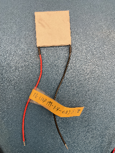
Peltier TE-127-1.0-2.5: 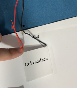
| peltier | Laird 387004685 (125W) | HP-199-1.4-0.8 (120W) | HP-199-1.4-1.15 (175W) |
|---|---|---|---|
| figure | 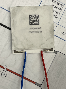 | 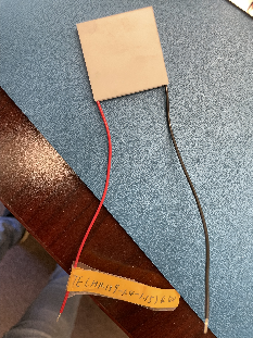 |
|
| properties | Qmax 125 W | Q max 120 W | Q max 175 W |
| data sheet | Link | Link | Link |
| measurements |
P~ 10W delta T =11 C (without load) |
P~9W delta T =12 C P~20W delta T =15 C |
P ~ 6W delta T = 6 C P~ 17.5W delta T = 9 C |
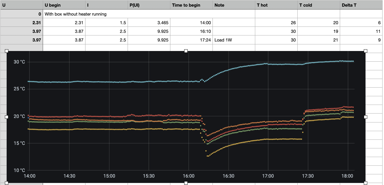
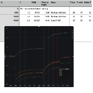
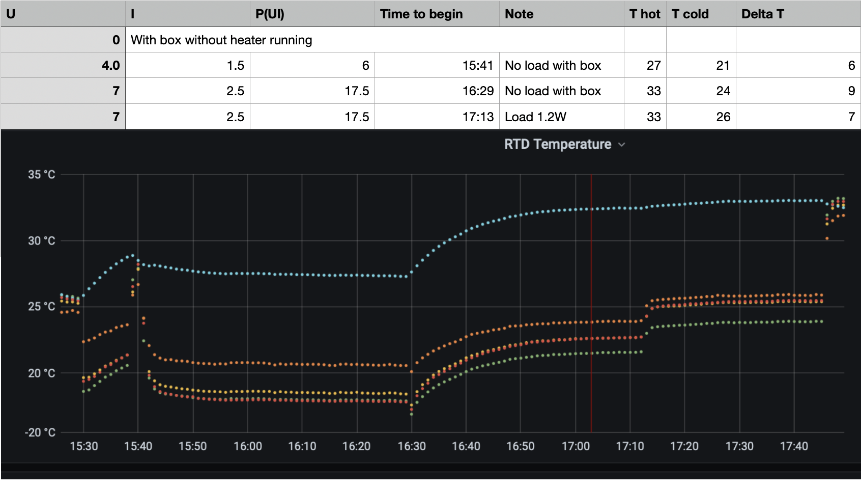
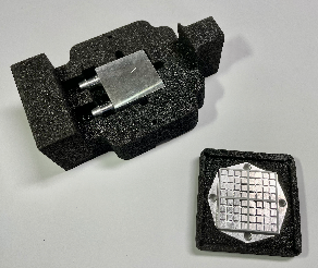
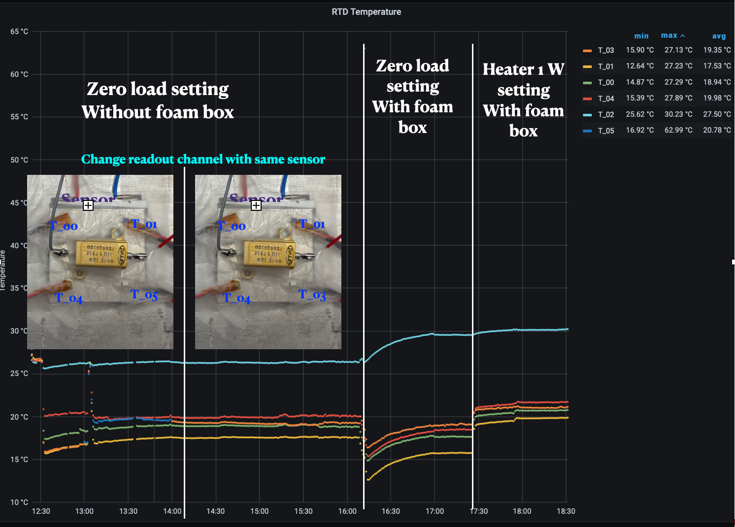
Preliminary Setup and Test Result
Empty load step up | With Heater | with foam box |
|---|---|---|
|  | 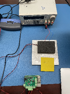 |
 |
|
Results
- Check the Temperature distribution on the Peltier, temperature distribution is not flat on the cold side of Peltier while running the Peltier
- foam box can help isolate the Peltier system and increase the temperature difference between hot side and cold side
- running load will increase the temperature on the cold side
Results from chiller:
Tests with cooling setting:
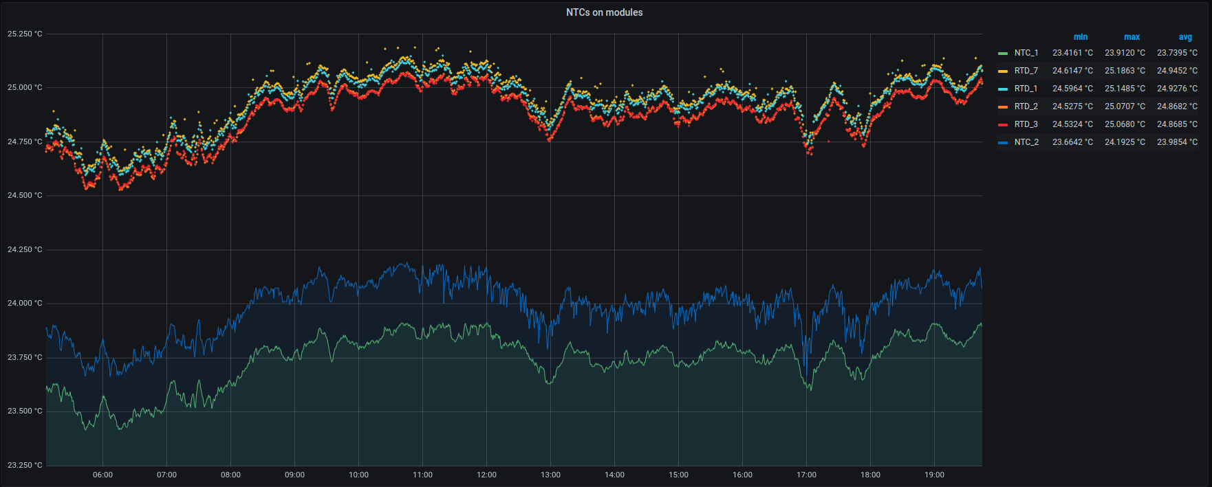
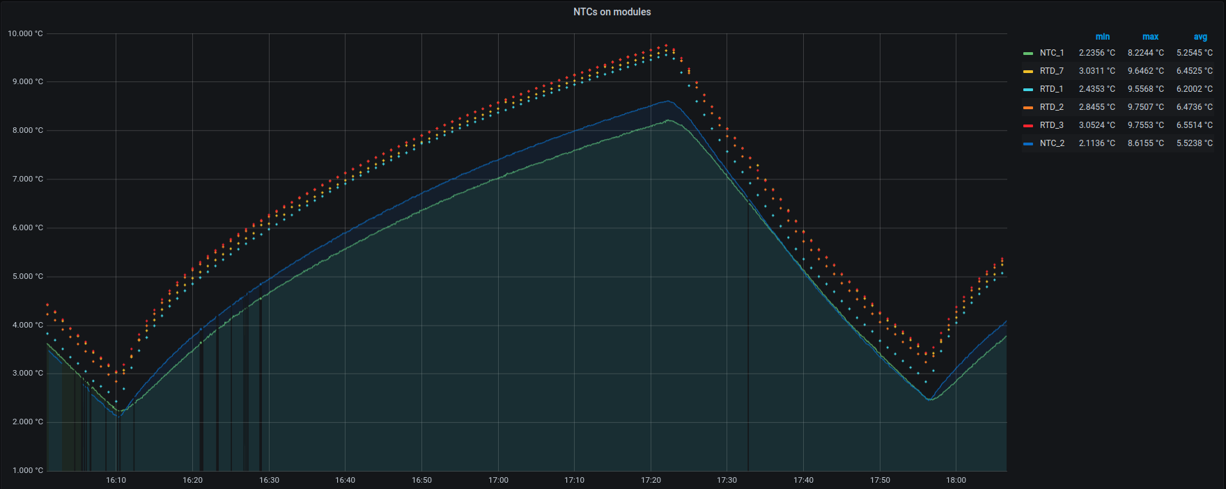
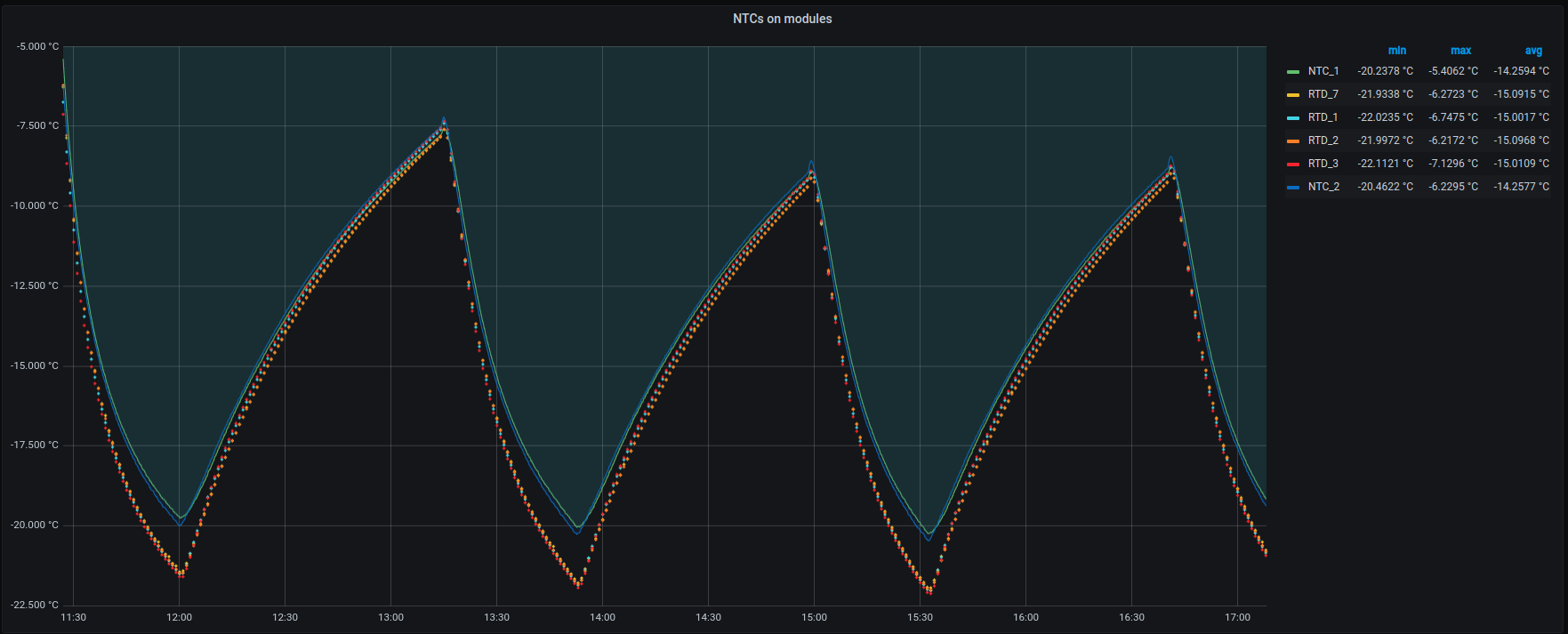
Temperature Agreements:
Tests where done to see if the NTC and RTD temperature data was consistent at or near operating temperatures. As can be seen there is a drift where the RTD reads 2 ℃ lower then the NTC. However at room temperature this difference is reversed and reads about 1 ℃ higher.
| Name in results | Sensor, Location | Accuracy | DataSheet |
|---|---|---|---|
NTC_1 | NTCG103JF103FTDS, On RD53A | ±.5 ℃ | https://product.tdk.com/system/files/dam/doc/product/sensor/ntc/chip-ntc-thermistor/catalog/tpd_automotive_ntc-thermistor_ntcg_en.pdf |
| NTC_2 | 192-103LEW-A01, Taped to mounting plate of RD53A | ±1℃ | https://www.mouser.com/ProductDetail/Honeywell/192-103LEW-A01?qs=F1jq4PciTHu1X2%252BS%2F4fB2A%3D%3D |
| RTD_7 | pT100, Taped to mounting plate of RD53A | ±.15 ℃ | https://www.mouser.com/ProductDetail/Heraeus-Nexensos/32208550?qs=MQgg6%252BVqoaOPAnuE2NwxiQ%3D%3D |
| RTD_1 | pT100, Taped to mounting plate of RD53A | ±.15 ℃ | https://www.mouser.com/ProductDetail/Heraeus-Nexensos/32208550?qs=MQgg6%252BVqoaOPAnuE2NwxiQ%3D%3D |
| RTD_2 | pT100, Taped to mounting plate of RD53A | ±.15 ℃ | https://www.mouser.com/ProductDetail/Heraeus-Nexensos/32208550?qs=MQgg6%252BVqoaOPAnuE2NwxiQ%3D%3D |
| RDT_3 | pT100, Taped to mounting plate of RD53A | ±.15 ℃ | https://www.mouser.com/ProductDetail/Heraeus-Nexensos/32208550?qs=MQgg6%252BVqoaOPAnuE2NwxiQ%3D%3D |
| Room temperature, no load on module | In fridge, no load on module | In freezer, no load on module. |
 |
|
|
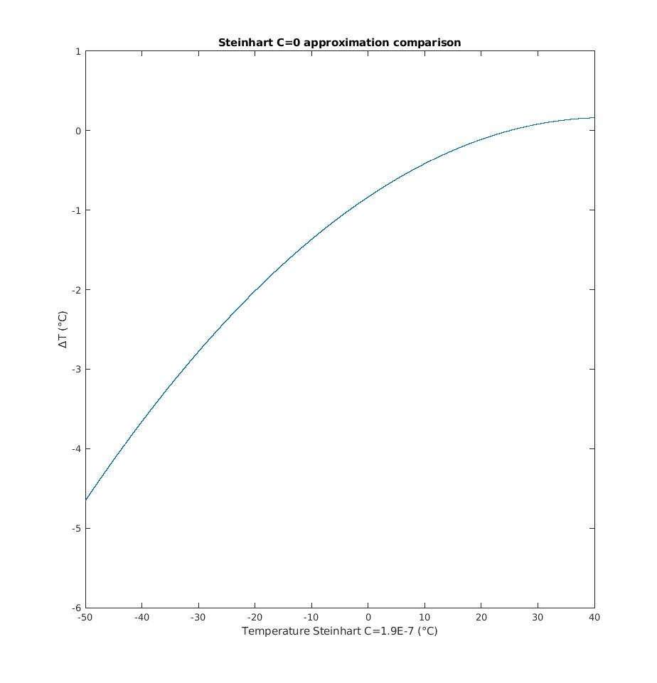
The NTC on the modules are type NTCG103JF103FTDS. More information about these modules can be found at https://twiki.cern.ch/twiki/bin/view/Atlas/ItkPixModuleTesting#Reading_out_the_NTC_Module.
However the data sheet and the twiki about the sensors do not agree about the relationship between the resistivity and temperature. The differences is plotted below. Note Δt is the Data Sheet value minus the twiki results. In all our code the temperature is calculated via the data sheet values.

With B = 3380, R0 = 10,000 Ohms and T0 = 25℃