You are viewing an old version of this page. View the current version.
Compare with Current
View Page History
« Previous
Version 6
Next »
3/7/2024
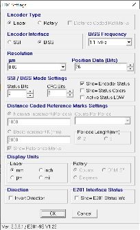
E201 Encoder setting
2/6/2024
Equipment need for testing:
As this device uses custom clipper chassis in the undulator hall, we will use a test controller for support in vacuum shop
- Use chassis SLAC PO 217843 for testing. This is a 1 channel stepper control chassis. CP10.
- M1 motor is terminated with DB15 male connector
- To connect M1 to chassis we need (from motor): DB15 M-F cable, DB15 female breakout, DB9 male breakout board, DB9 F-F cable to chassis. Chassis motor channel is terminated DB9 male
- To connect M1 or M2 motor encoder, use E2019S RLS encoder tester.
- All limit switches are wired into one DB15 M connector. To connect limit switches to the chassis need DB15 F-M cable. Chassis is DB15 F. We need two DB15 breakout boards to extract the correct limit switch signal for the chassis. We need a DB15 F-M to go from breakout board to chassis. Need 3 wired to extract the correct limit switch signal on the breakout board.
- M2 motor is terminated with DB9F connector.
- To connect M2 to chassis we need (from DB9F connector) a DB9M breakout board, DB9M chassis. DBF-F cable with a DB9 male breakout board
Aerotech configuration files. SLAC PO217843 controller is set up with IP: 192.168.1.16. Set up you laptop IP in same subnet. These are open loop setups
BOD1 M1 (X)
BOD1 M2 (Y)
Limit switch wiring:
Limit switches are wired on pins 1,2 and 9 on the aerotech chassis side.
For M2 motor limit to controller
3→1
4→2
11→9
12→9
This configuration has CCW limit is towards motor and CW limit towards chamber
Aerotech motor wiring for M2 motor
DB9F on motor to DB9 on controller.
4→3
3→ 2
2→ 3
1→1
Moving M2 motor in positive on aerotech, moves CCW on the rear of motor shaft. This means we are going towards undulator hall wall. Encoder reading increases.
TODO:
- solder limit switch for M1