3/7/2024
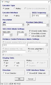
E201 Encoder setting
X axis fiducialization notes:
Movements at 0.1mm/sec speed
IN limit switch (Shows up as CW in aerotech) (Switch closest to BOD body) reads 54.734mm from encoder tester
OUT limit switch (Shows up as CCW in aerotech) (Switch away from BOD body) reads 32.976 mm from encoder tester
MPS limit switch (close to OUT limit switch) 42.21mm from encoder tester
MPS limit switch (close to IN limit switch) from encoder tester
Important positions:
- Motion limit - 54.73mm
- MPS stay clear limit switch - 52.9mm (around)
- Vertical wire position - 41.7mm
- Vertical wire + 0.5mm - 41.24mm
- YAG edge - 39.6mm
- YAG edge + 2mm - 37.62mm
- Motion Limit - 32.9mm
- MPS limit switch - 42.21mm
Y axis position
- Motion Limit- 23.27mm
- Vertical wire position - 22.27mm
- Motion Limit - 20.93mm This will need to be readjusted to be actuated at 1mm from wire center position

2/6/2024
Equipment need for testing:
As this device uses custom clipper chassis in the undulator hall, we will use a test controller for support in vacuum shop
- Use chassis SLAC PO 217843 for testing. This is a 1 channel stepper control chassis. CP10.
- M1 motor is terminated with DB15 male connector
- To connect M1 to chassis we need (from motor): DB15 M-F cable, DB15 female breakout, DB9 male breakout board, DB9 F-F cable to chassis. Chassis motor channel is terminated DB9 male
- To connect M1 or M2 motor encoder, use E2019S RLS encoder tester.
- All limit switches are wired into one DB15 M connector. To connect limit switches to the chassis need DB15 F-M cable. Chassis is DB15 F. We need two DB15 breakout boards to extract the correct limit switch signal for the chassis. We need a DB15 F-M to go from breakout board to chassis. Need 3 wired to extract the correct limit switch signal on the breakout board.
- M2 motor is terminated with DB9F connector.
- To connect M2 to chassis we need (from DB9F connector) a DB9M breakout board, DB9M chassis. DBF-F cable with a DB9 male breakout board
Aerotech configuration files. SLAC PO217843 controller is set up with IP: 192.168.1.16. Set up you laptop IP in same subnet. These are open loop setups
BOD1 M1 (X)
BOD1 M2 (Y)
Limit switch wiring:
Limit switches are wired on pins 1,2 and 9 on the aerotech chassis side.
For M2 Y motor limit to controller
1→1
2→2
9→9
10→9
This configuration has CCW limit is towards bottom and CW limit towards top
For M1 X motor limit to controller
3→1
4→2
11→9
12→9
This configuration has CCW limit is towards motor and CW limit towards chamber
Aerotech motor wiring for M2 motor
DB9F on motor to DB9 on controller.
4→3
3→ 2
2→ 3
1→1
Moving M2 motor in positive on aerotech, moves CCW on the rear of motor shaft. This means we are going towards undulator hall wall. Encoder reading increases.
TODO:
- solder limit switch for M1