Introduction
Front View:
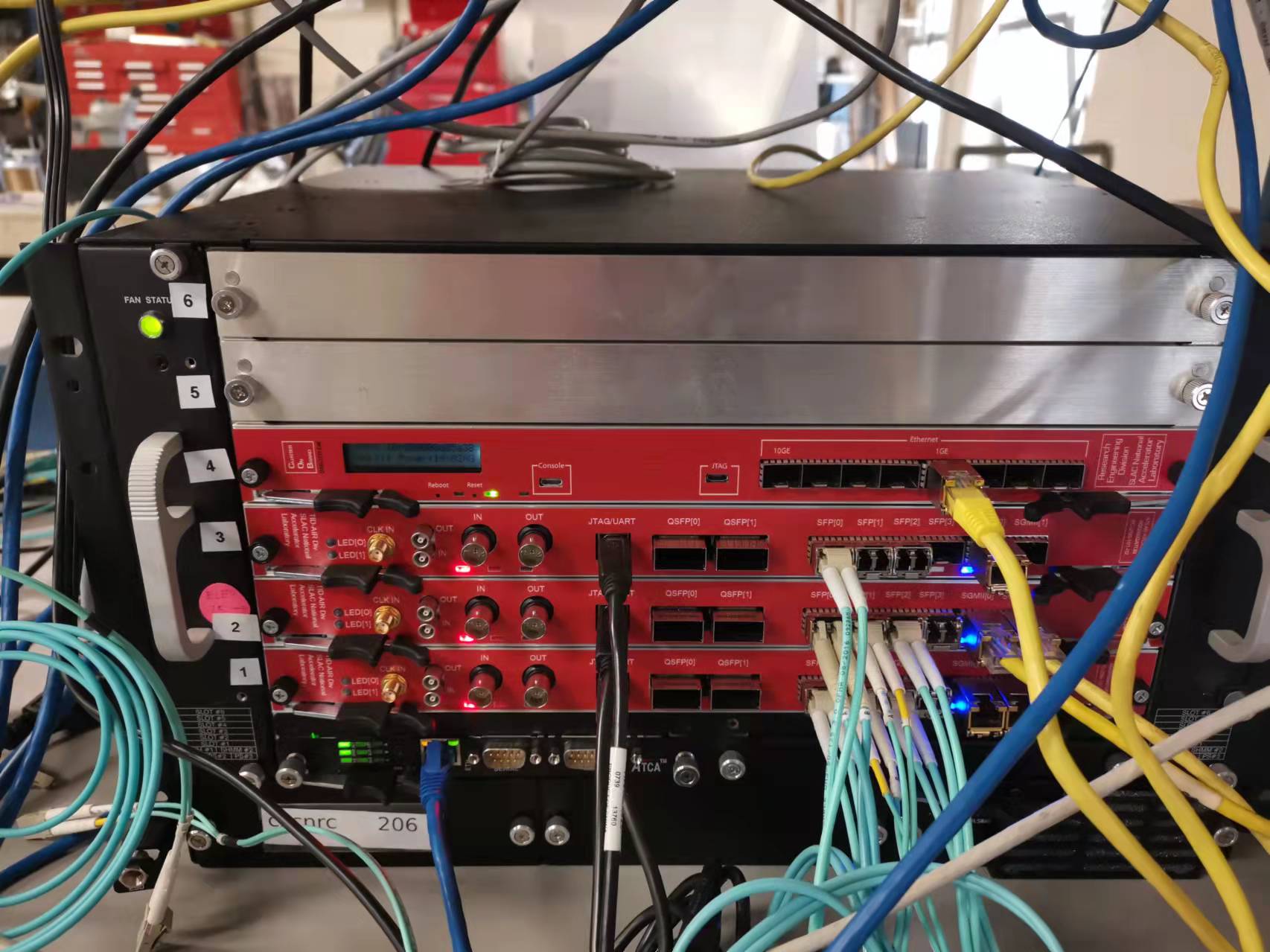
From bottom to top, this ATCA crate has 6 slots in total. The slot 1, 2, 3 have the linkAgg board, while the slot 4 has COB (RCE-Gen3).
For the linkAgg board front panel, there are 4 different interfaces:
1) 2x SFP Ethernet (yellow ethernet cable): used for slow controlling the linkAgg FPGA internal register;
2) 4x High speed SFP+ : optical fiber cable (cyan cable) connected to backend DAQ. Speed depends on the protocol. For example, lpGBT protocol is 10Gbps, Pgpv4 is 6Gbps;
3) 2x High speed QSFP+: 1x QSFP+ port is equivalent to 4x SFP+; all others are same as SFP+ ports;
4) JTAG (USB type A black cable): to program the linkAgg FPGA.
Useful IP Addresses
LinkAgg board
the hardware project page: https://confluence.slac.stanford.edu/display/AIRTRACK/PC_256_101_02_C01
| linkAgg Board # | MAC 4 | IP 1 | MAC 5 | IP 2 | hardware description |
|---|---|---|---|---|---|
C01-01 | 08:00:56:00:4f:82 | 192.168.4.66 | 08:00:56:00:4f:83 | 192.168.4.67 | ATLAS ATCA Link Aggregator Board C01-01 - HWDB 267390223 |
| C01-02 | 08:00:56:00:4f:88 | 192.168.4.72 | 08:00:56:00:4f:89 | 192.168.4.73 | ATLAS ATCA Link Aggregator Board C01-02 - HWDB 267390220 |
| C01-03 | 08:00:56:00:4f:8e | 192.168.4.78 | 08:00:56:00:4f:8f | 192.168.4.79 | ATLAS ATCA Link Aggregator Board C01-03 - HWDB 267390217 |
*Note, the MAC 4 and MAC 5 are for the two front-panel ethernet ports, and MAC0-3 are for the ATCA fabric backplane, which we are not using so far
ATCA crate
| ATCA Name | IP | Location | access |
|---|---|---|---|
| 6-Slot ASIS | 192.168.4.2 | B84, room B231 (lab C) | root/NA |
| 2-Slot ASIS | 192.168.4.210 | B84, room B231 (lab C) | root/NA |
FPGA firmware for the linkAgg board
the firmware is officially released here: https://github.com/slaclab/atlas-rd53-atca-dev/releases
current lpGBT emulator firmware for linkAgg is AtlasAtcaLinkAggRd53Rtm_EmuLpGbt-0x03010000-20220204084052-ruckman-6bfc5ca.bit
current PGPv4 firmware for linkAgg is AtlasAtcaLinkAggRd53Rtm_Pgp4_6Gbps-0x03010000-20220204084122-ruckman-6bfc5ca.bit
*the XXX.bit file can be used to program the FPGA through the JTAG interface with vivado software
*the XXX.mcs file can be programmed to a permanent memory of the linkAgg firmware, so that the FPGA can automatically get firmware from the memory when power on
Software to slow control the linkAgg Firmware
the rogue-based GUI software is also included in the same github project of the firmware: https://github.com/slaclab/atlas-rd53-atca-dev
in order to run this software, need to install rogue package at first: https://slaclab.github.io/rogue/installing/anaconda.html#
Instruction to install the rogue
install anaconda at first:
$ wget https://repo.anaconda.com/archive/Anaconda3-2020.07-Linux-x86_64.sh
$ bash Anaconda3-2020.07-Linux-x86_64.sh


Use the following command to add anaconda to your environment. This can be added to your .bash_profile.
$ source /path/to/my/anaconda3/etc/profile.d/conda.sh
install rogue enviroment:
$ conda create -n rogue_tag -c tidair-tag -c tidair-packages -c conda-forge rogue
Enable the rogue enviroment
$ conda activate rogue_tag
Download the linkAgg github project
$ git clone --recursive git@github.com:slaclab/atlas-rd53-atca-dev
Run the software:
$ cd atlas-rd53-atca-dev/software/
$ python3 scripts/gui.py --ip <IP add> --remoteDevice <firmware_type>
the firmware_type is LinkAggLpGBt or LinkAggPgp or Kcu105 or Zcu102. You can find the IP address from here: linkAgg boards IP
For example, python3 scripts/gui.py --ip 192.168.4.72 --remoteDevice LinkAggLpGBt