...
Once the setup is complete, follow these instructions to test and generate/save the needed report. Make sure to have a sufficiently large USB flash drive connected to any of the USB input ports on the left hand side of the machine, towards the rear.
Initial setup:
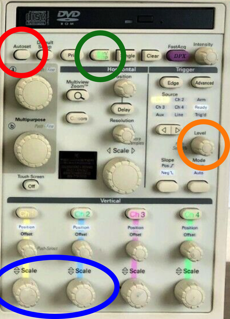
- Use the Autoset button to initially set parameters of interest.
- You should now see 2 signals, one in yellow and one in blue, for each of the signals
- Adjust the Scale knobs until the scale reads 300mV in the bottom left corner of the screen
- Now use the Level adjustment to set the trigger. You do this by watching the yellow arrow located on the right side of the display (next to the channel 1 yellow signal). You want the arrow to be on the positive side of the signal (imagine sin(π/4) or so), if you are in the correct place the "trig" light directly above the know should illuminate.
- Now you can run the first test, go to Analyze on the top toolbar, then **Something Jitter** then Jitter and Eye Analysis (DPOJET) (about 5 or 6 down from the top), then One Touch Jitter.
- This will take a moment, but it should display 4 plots, with the eye diagram in the bottom right corner, bathtub shape, and some other plots. Channel 1 is the default, so it will automatically start with Channel 1.
- Actually, we want the differential channel which is Math1 = Ch1 - Ch2. Do this by going to to Select → Source(s) → Math → 1 → Apply. Now we can take data.
Taking data:
- If the Run/Stop button is not on, press it again to get the signal going again.
- Clear → Recalc to get the new measurement with Math1.
- Go to Reports in the bottom left corner of the screen.
- Select "Save As" on the right side of this panel. From here you can select your USB drive if you wish. The naming convention should go as follows: SN${SerialNumber}_Chn${Channel}_${DataPort}. For example, if you were testing cable DP001, on the data1 output
...
- and channel 2 it would read: SNDP001_Chn2_Data1.
- Now you can move on to test Channel 2.
- After the report is saved and the browser window is closed, close the "plots" window to make the 4 plots that you saw go away. You should now see the signal again.
- Press the Run/Stop button to get the signal going again.
- Change the source to channel 2 by using the < | > arrow button located just to the left and above the level knob.
- Now you will be using the level knob to set the trigger level for the blue signal, or channel 2. Again just shoot for the positive side of the signal and verify the "trig" light is on
- Once this is done, go down to the window that you selected Reports on and press the Results option. ????Choose the config panel and hit the channel 2 button to add it to the list underneath, then choose "Apply All".
- Press the "ReCalc" button on the right of this window.
- This should start the entire process over again, once it's finished and now plots pop up, you can go back to the Reports window, and save the report modifying the save name accordingly.
- Now just remove the quick connect cables from the cmd data ports and move to data0, you can just go back to step 7, hit "ReCalc" and it will scan again, save the report and change back to channel 1.
- If you open the report, you should have at the very least the signal amplitude, eye height, and eye width @ 10e-12 BER as a comparison, as well as the oscilloscope signal, eye diagram, and bathtub width.
- Repeat steps 1 - 5 for CMD and data0 - data3 channelsYou only need to start all the way over when you change USB cables, after cmd, data0, data1, data2 and data3 is scanned and the reports are saved. You should also not have to turn off anything until the very end, you can unplug and plug in the new cables on the fly .
Update:
...
- (especially efficient if you have the quick release SMA plugs).
Debugging tips if you see an eye that is not open when you expect it to be (or anything else that is strange):
- Reset the transmission links on the KCU105 board (bottom GUI panel)
- Try redoing the 1 touch jitter. Sometimes this resets some settings and fixes the problem.
- Check connectivity of the SMA cables
- Try again on a different day, when the stars are aligned differently
Results for the first batch of 44 DP cables can be found here.
...