These are the new instructions for how to use the gas jets. This procedure will supersede the "How to use gas jets" and "How to DPS with gas jets" pages.
Hardware requirements:
- Gas bottle of selected gas species. Needs to have >1200psi if you plan to run the jets that high.
- N2 available in the 6 pack if you plan to run with H2
- Regulator - there are multiple available
- 100 to 1200 psiG (max 3000psiG, but we only run up to 1200)
- -30psiG - ?? psi (for low pressure, and the ability to run to real 0, not 0 psiG
Note: Approval to operate with hydrogen needs to be given. The authorization checklist is here: https://docs.google.com/document/d/13LvuOP7FBSUg4rawcie_g3sfOF0nirf4Z7H8PEaZ4EE/edit
For any testing, we use helium. Particularly for testing when in access- exceptions can be given if following a reviewed and approved procedure.
Step-by-step guide
1. Prepare the DPS system
- Verify both US-DPS and DS-DPS pumps are running and operating as normal.
- Open DPS full schematic (from the Li20 Vacuum page, or the Gas jet control panel)
- Also check VPIO:LI20:3164 to ensure the ion pump is on.
- Click the "DPS Status Monitor" button and confirm the watcher status is ON/green
- Figure 1 shows how the DPS looks under nominal operation.
- Start a strip tool and load the file: DPS_Gasjet_Pressures.stp (Or click button on Gas jet control panel)
- Find the VGCM:LI20:M3203:PMONRAW pressure - this is the 10 Torr capacitance manometer gauge that will provide the IP pressure.
- Ensure the 10 Torr CM gauge is zeroed: VGCM:LI20:M3203:P should be reading 0 Torr on the strip chart.
- If not - this must be zeroed using the rack controller.
- If not - this must be zeroed using the rack controller.
- Find the VGCM:LI20:M3203:PMONRAW pressure - this is the 10 Torr capacitance manometer gauge that will provide the IP pressure.
- Leave the downstream Be window OPEN, this will help
- NOTE - this advice could change after the full characterization of the gas jet if it is found to be more beneficial to close the window. If the 3250 valve interlock keeps tripping, then the Be window can be inserted to reduce the pressure in the DS DPS.
- NOTE - this advice could change after the full characterization of the gas jet if it is found to be more beneficial to close the window. If the 3250 valve interlock keeps tripping, then the Be window can be inserted to reduce the pressure in the DS DPS.
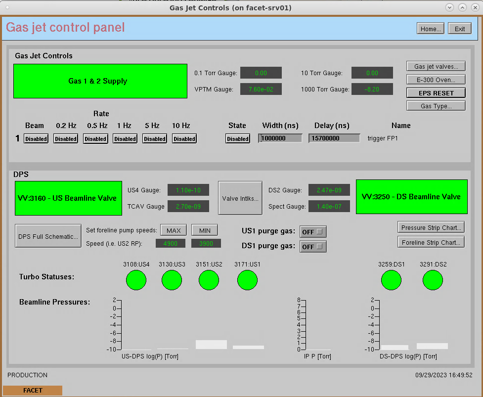
- Open the gas jet control panel from facethome: LI20 → Experiment → Gas Jet Controls... (Figure 2)
- Ensure the "Gas 1&2 supply" is green - this tell us that the EPS has not faulted. If it is red, try clearing the fault by hitting "EPS RESET". More details on the interlock statuses can be found in the "E300 Oven..." page
- If this does not fix it, it needs some expert attention which probably means talking to Doug Storey.
- Set the foreline pump speeds to MAX
- Set the gas type to Helium. There is no calibration curve for hydrogen, so use helium for both He or H2.
- If using hydrogen gas, then set the US1 and DS1 purge gas valves to ON (you will need to open the N2 gas bottle in the gallery later on)
- Ensure the "Gas 1&2 supply" is green - this tell us that the EPS has not faulted. If it is red, try clearing the fault by hitting "EPS RESET". More details on the interlock statuses can be found in the "E300 Oven..." page
- In the gallery:
- Zero the 10 Torr capacitance manometer gauge if necessary.
- If using hydrogen: Start the purge gas flowing - open the nitrogen 6 pack main valve and ensure that there is ~10 PSIG pressure on the regulator. Check the other in-line valves are open
- You can verify the flow is flowing by opening: DPS Full Schematic → US1 and DS1 roughing pumps → More..., and read the "N2 Flow" PV. It should be reading ~4 Pa.m3/s
- You can verify the flow is flowing by opening: DPS Full Schematic → US1 and DS1 roughing pumps → More..., and read the "N2 Flow" PV. It should be reading ~4 Pa.m3/s
- Prepare the gas delivery - next section.
Figure 1: Nominal vacuum state, before gas jet operations
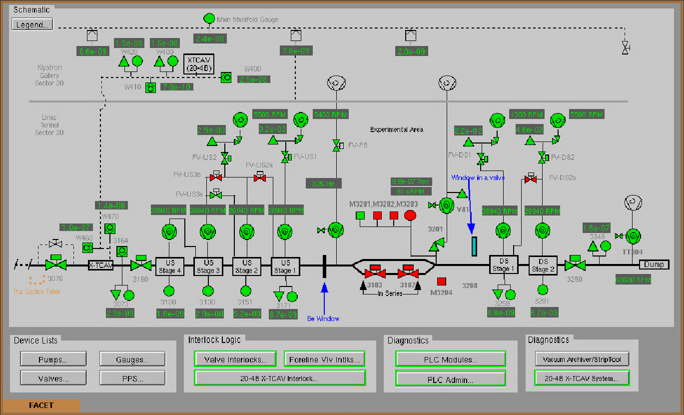
Figure 2: Gas jet control panel
2. Prepare the gas delivery
- In EPICS, from the Gas jet control panel - open the "Gas jet valves..." and ensure all are "OFF"
- In the gallery:
- Connect the gas bottle: Figure 3 -IF YOU DON"T KNOW WHAT YOU ARE DOING, THEN DON'T DO IT!!
- Ensure that your chosen regulator is connected to the fill line. If not, then change this.
- You MUST have training from Juan to change the regulator (VCR connectors)
- Connect the chosen regulator to the bottle
- You MUST have course 172 - Compressed Gas Safety in person training to change bottles/regulators
- Open the bottle and set the regulator to the desired operating pressure
- You MUST have course 122 - Pressure System Operator web training to operate the regulator
- Open the manual valve just downstream of the regulator
- Check that the valve labeled "Bottle" is closed".
- Slowly open the manual valve labeled "Release" for a few seconds to purge some gas through the line. Close it.
- Ensure that your chosen regulator is connected to the fill line. If not, then change this.
- Check that the tiny scroll pump by penetration 20-12 is running- Figure 4
- It vibrates slightly, so you can feel it with your foot
- Open the fill valve (ON) in Epics
- Open the Drain valve (ON) in Epics
- Drain the fill line
- Open the manual valve on the drain line labeled "Vacuum Pump"
- Leave for a few minutes to evacuate the line of anything present in it
- Close the drain valve (Off)
- Close the manual valve on the drain line. This valve will need to be opened to totally evacuate the gas line at the end of the shift or if you need to change gas species. But isn't needed to drain pressure to lower values.
- Open the manual valve on the fill line labeled "Bottle".
- Confirm the second pressure gauge on the fill line (top left in image) rises to approximately what you set the regulator to. It won't be exact. Use the regulator at the bottle as the reference pressure NOT this second gauge.
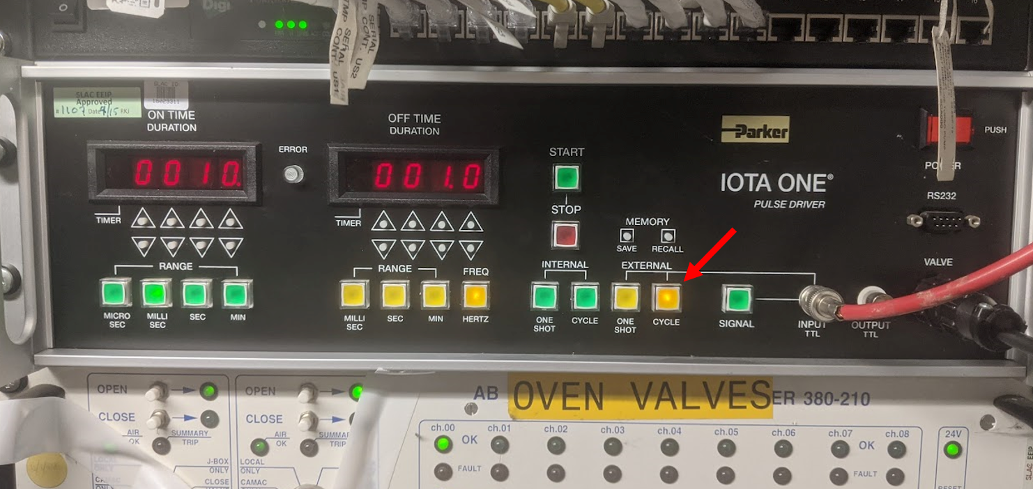
- Turn on the IOTA controller in Rack FKG20-22
- Power on
- Ensure that is is set to use "CYCLE" under the "EXTERNAL" trigger. Not one shot. See Figure 5. The button that is illuminated should be illuminated.
- This will allow the jet to fire at the time and width as set in the control system
- Note: You can also set to internal triggers and adjust using front panel for testing.
- Note: You can also set to internal triggers and adjust using front panel for testing.
- Connect the gas bottle: Figure 3 -IF YOU DON"T KNOW WHAT YOU ARE DOING, THEN DON'T DO IT!!
NOTE ABOUT CHANGING THE REGULATOR
The regulator may be changed by disconnecting the VCR fittings. Training from Juan should be undertaken before doing this.
You are now done in the gallery.
Figure 3: Gas bottle and fill line
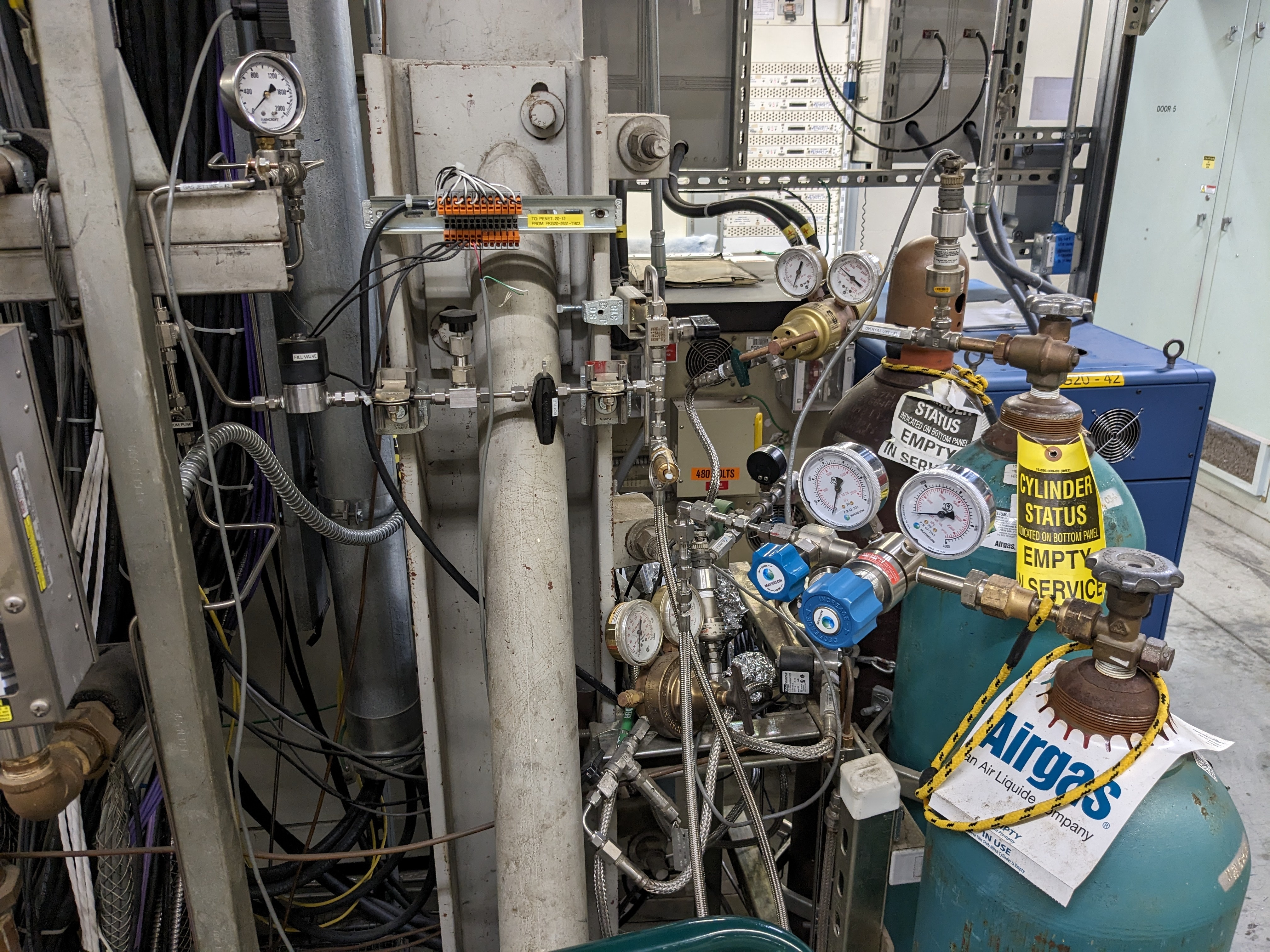
Figure 4: Drain line and scroll pump
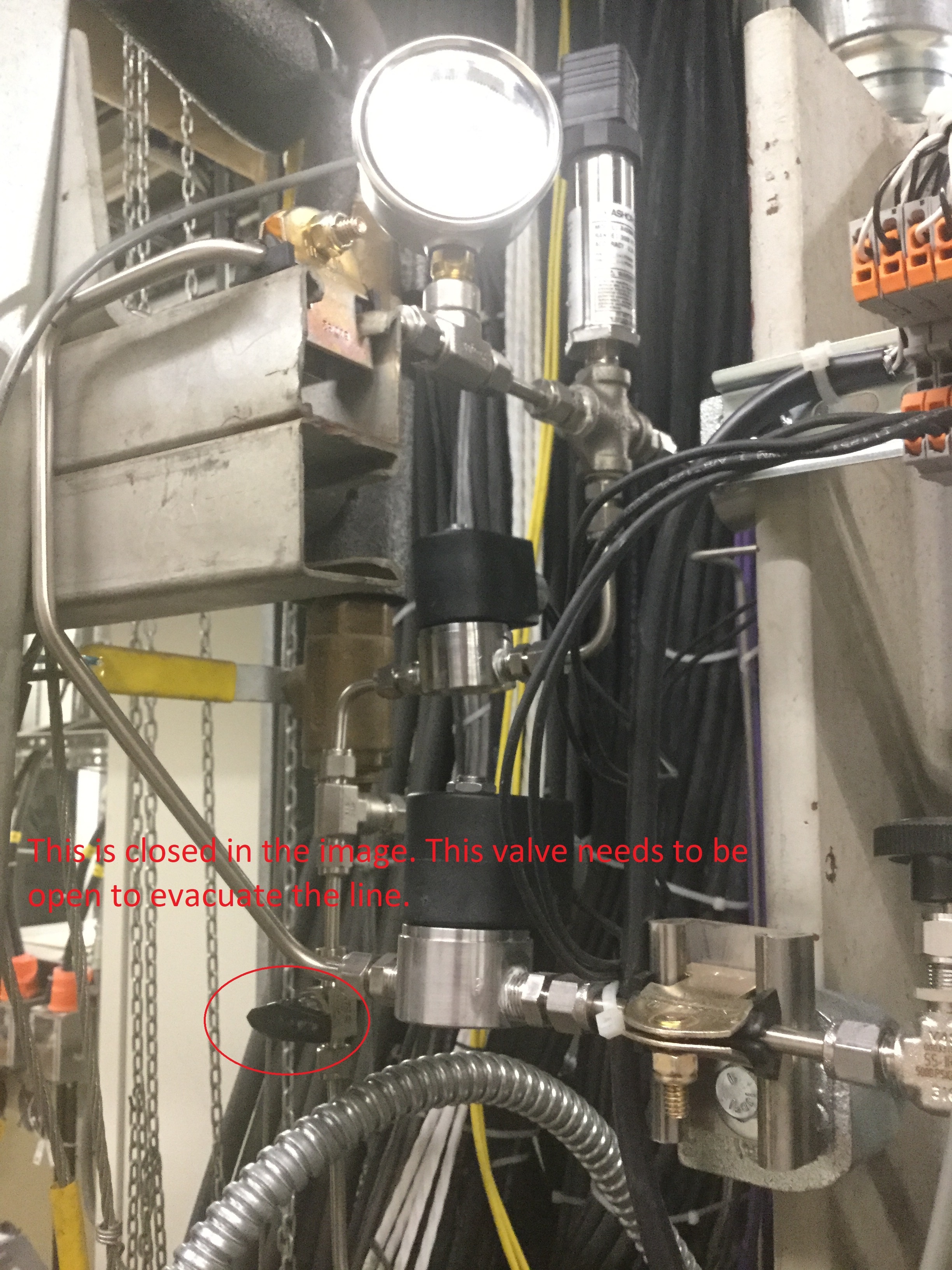
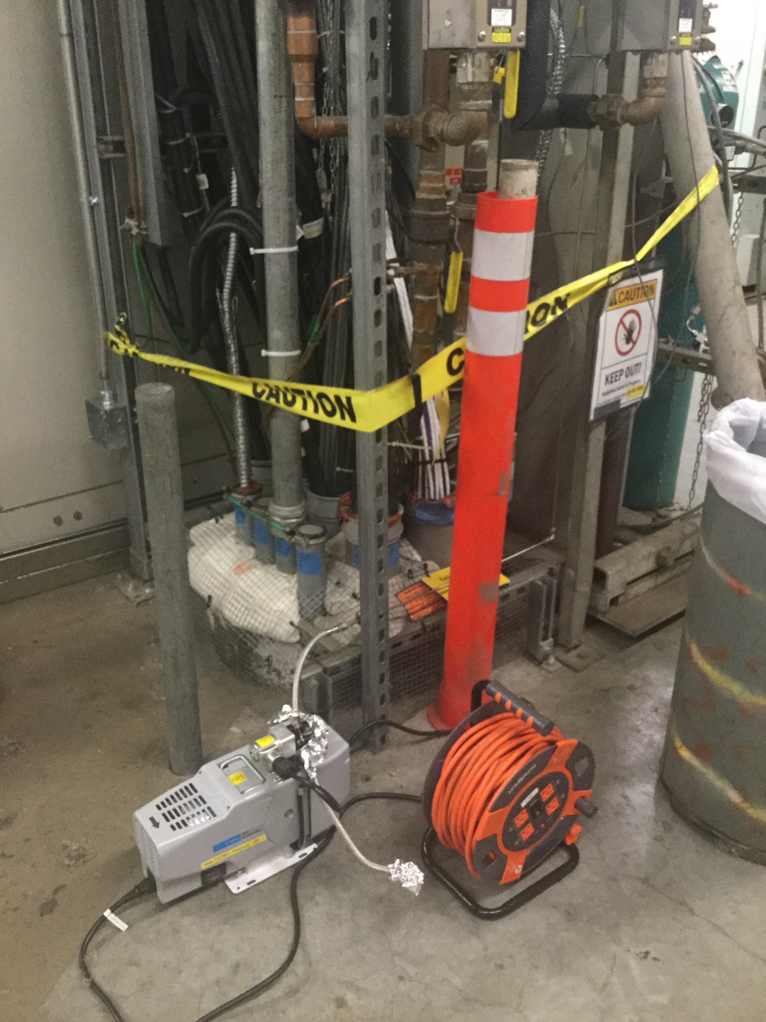
Figure 5: IOTA controller and it's correct set up
3. How to operate the jet
- Open the Gas jet controls panel in EPICS: LI20 → Experiment → Gas Jet Controls... (Figure 2)
Summary of features:- Gas 1 & 2 Supply: This goes red when the EPS is faulted and closes the Fill valve.
- Gas jet valves...: Opens panel to control the fill, drain, and PB valves.
- E-300 Oven...: Gives more details on the EPS faults.
- EPS RESET: this resets the EPS and opens the EPS valve, and makes the "Gas 1 & 2 Supply" status green.
- Gas Type...: Changes the calibration for gas type. There is no calibration for H2, so use He in this case.
- Rate: Use to select the rate that the jet fires at. Only select one at a time.
- State: Disabled == jet off. Enabled == jet firing
- Width: 1ms (1000000 ns) is standard opening time
- Delay: 15.7ms (15700000ns) is standard delay
- Fire the gas jet ONCE (using steps a and b below) to ensure the jet fires and the DPS responds appropriately.
Figure 6 shows the strip chart under some nominal conditions.- Turn on the PB Valve Hi. Pres. Line in Epics
- Set the rate to 0.2 Hz
- Set state to Enabled, and wait ~5s for IP pressure to spike, then disable the state to stop.
- VGCC:LI20:3108:US4 should stay below 1e-9 Torr
- VGCC:LI20:3291:DS2 should stay below 1e-5 Torr
- VGCC:LI20:3073 should see minimal change and stay below 5e-8 Torr
- Fire the gas jet for a minute or so and watch the strip chart. If all continues to look good then you are good to fire at will.
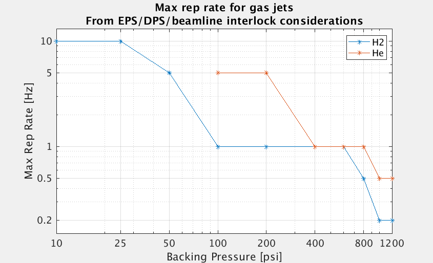
- Set the rate and fire the gas jet as desired. The table at the bottom of the page can help to set the desired rate.
- Set the rate by selecting only one of the provided rate options.
- Set the "State" to Enabled" to start firing the jet. Disable stops the jet
- For best vacuum behavior, Stop the jet when not actively taking data or tuning.
- Especially, for hydrogen as the gas can build up in the roughing pumps and cause the loss of pumping efficiency and degrading DPS performance over time.
- Especially, for hydrogen as the gas can build up in the roughing pumps and cause the loss of pumping efficiency and degrading DPS performance over time.
TROUBLESHOOTING:
- If the "Gas 1 & 2 Supply" indicator goes red then there is an EPS fault:
- Stop the jets
- Check that there is not a DPS issue
- Wait for the pressure to decrease
- Hit "EPS RESET" to reset the EPS. The gas indicator should turn green
- More details can be found in the E-300 Oven panel
- No need to call ACR for this type of fault
- If the Beamline valve indicators go red, then there is a beamline pressure problem.
- Stop the gas jets
- CALL ACR to let them know what is going on.
- Ensure all the turbos are running - all turbo indicators are green, or see more details in DPS Full Schematic
- Wait for the pressures indicated to decrease and change back to green
- Open the Valve Intlks page (from the LI20 Vacuum page) and reset interlocks, then you can reopen the beamline valve from the DPS Full Schematic page if all valve interlocks are cleared.
- If any turbo indicators turn red then call for help. More details can be found in the DPS Full Schematic
THINGS TO WATCH OUT FOR:
- If the lone cold cathode gauges shut themselves off, then turn them back on. If pressure reads above 1e-3 Torr then turn it back off.
- If a CC gauges on 3171 or 3259 are cycling on and off, then force them to stay off (or on if it is in a safe pressure zone)
- Change the control mode to Off, then turn CC HV off.
- Watch the PB and oven turbo temperatures
- Watch CC3073 to see if it ever changes.
- Watch if the DPS foreline valves trip in and the turbos shut off. If this happens DO NOT TRY TO FIX unless you are Doug, or someone knowledgeable about the DPS system.
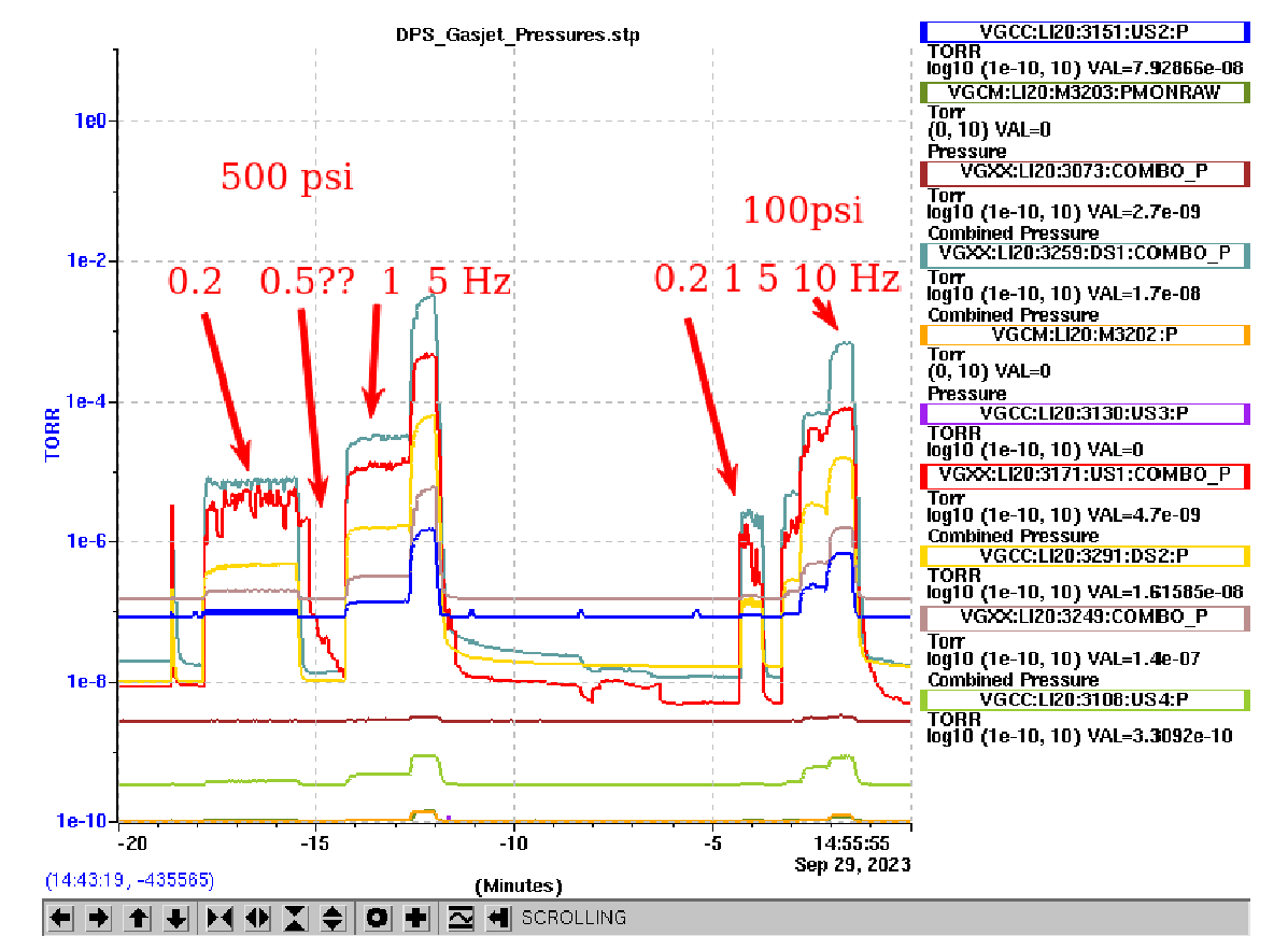
Figure 6: Beamline pressures under nominal conditions with H2 gas
4. How to reduce pressure or get into safe state to move the gas jet assembly
- Stop the jet by setting to disabled.
- Close Fill valve.
- Check that the Picnic Basket (EPS) valve is Open (i.e. Gas 1 and 2 Supply is green)
- Open drain valve. This reduces pressure in the line to 1 psig.
- Note - if you are standing by the bottles then there will be a loud noise as gas escapes through the PRV.
- The manual valve should be closed (and stay closed). You just need to reduce the pressure, not totally evacuate the line.
- Wait a moment for the pressure to drop. Now it will be safe to move the gas jet assembly.
- Close the drain valve.
- Set the regulator pressure, or move the gas jet assembly. Or continue to next step to completely shut down the system or swap the regulator.
5. How to shut down after gas jet operation at end of shift or before changing gas species/regulator
- Use the previous step to stop the gas jet and reduce the pressure in the gas line.
- Close the valve on the gas bottle.
- Release the residual line pressure through the blow-off line by slowly opening the manual valve.
- Close the valve labeled "Bottle".
- If shutting down for the day:
- Open the drain valve in Epics
- Open the manual valve to the scroll pump to totally evacuate the line.
- Leave open for a few minutes.
- Close the manual valve on the drain line and drain valve in Epics.
- Close the PB valve on Epics
- Return the DPS to nominal operation (next section)
- If replacing the regulator or gas bottle: (You need the proper training to do this step)
- Ensure the regulator shows 0 pressure
- Disconnect the regulator from the fill line at the VCR fitting
- Remove the regulator from the bottle - discard the used gasket.
- Install the new regulator on the bottle
- Reconnect the new regulator with a new gasket (finger tight, then tighten a further quarter turn)
- Open the valve on the bottle
- Purge some gas through the blow off line (for a few seconds) and set the desired regulator pressure
- Open the valve labeled bottle
- Open the fill line valve on Epics
- You can confirm the pressure rises on the valve on the fill line
- You should be ready to fire the gas jet now
- Confirm: Drain valve is closed, Fill line is open, PB Valve is open
- Confirm: Drain valve is closed, Fill line is open, PB Valve is open
- If changing the gas species:
- Use the above procedure, but evacuate the gas line to remove all of the
Note - If there are any issues with the shutdown please contact Doug right away. It's important that we "de-energize" the system and pump out the gas if this is left unattended.
6. Return DPS to nominal state
- Ensure the jet is off, all gas jet valves closed, system drained, and bottle closed.
- Stop the purge gas from the Gas jet control panel, if this was on.
- Set gas type back to Nitrogen from the Gas jet control panel.
- Set the foreline pump speed to MIN.
- Remove the Be window (if it was inserted)
- In the gallery
- Close the nitrogen 6 pack main valve (if you used purge gas)
- Ensure the gas system is depressurized and valves closed (from the above procedure)
- Turn off the IOTA controller
- The DPS should be back into it's nominal state again (Figure 1).
- Call ACR to tell them that gas delivery is complete and everything is back to nominal state
At the end of the shift confirm:
- All valves in Epics are closed
- Fill valve, drain valve, PB valve
- Gas jet state is set to disabled
- All manual valves are closed
- Gas bottle and regulator valve
- N2 6-pack bottle (bottle and manifold) and regulator valve
- Valves labeled: "Vacuum pump", "Bottle", and "Release"
- The scroll pump should always stay on
Maximum operating rates
(05/17/24) Gas jet and static fill running together

Information needs to be updated for the present gas jet conditions.
Helium characterization from 7/16/2022 (obselete):
http://physics-elog.slac.stanford.edu/facetelog/show.jsp?dir=/2022/28/16.07&pos=2022-07-16T00:15:53
The following chart was acquired 07/15/2023, but with the timing width = 10ms, and no purge gas on the DPS. So this is now obsolete, but included for reference.
This schematic covers all the IP Area gas and vacuum systems. (March 16th 2022). Red valves are installed now but we would like to modify to move the EPS valve to the location of the isolation valve (work in progress).
Related articles
How to perform a static fill with DPS