You are viewing an old version of this page. View the current version.
Compare with Current
View Page History
« Previous
Version 2
Next »
The setup for the VME based BPMs can be found in Figure 1.
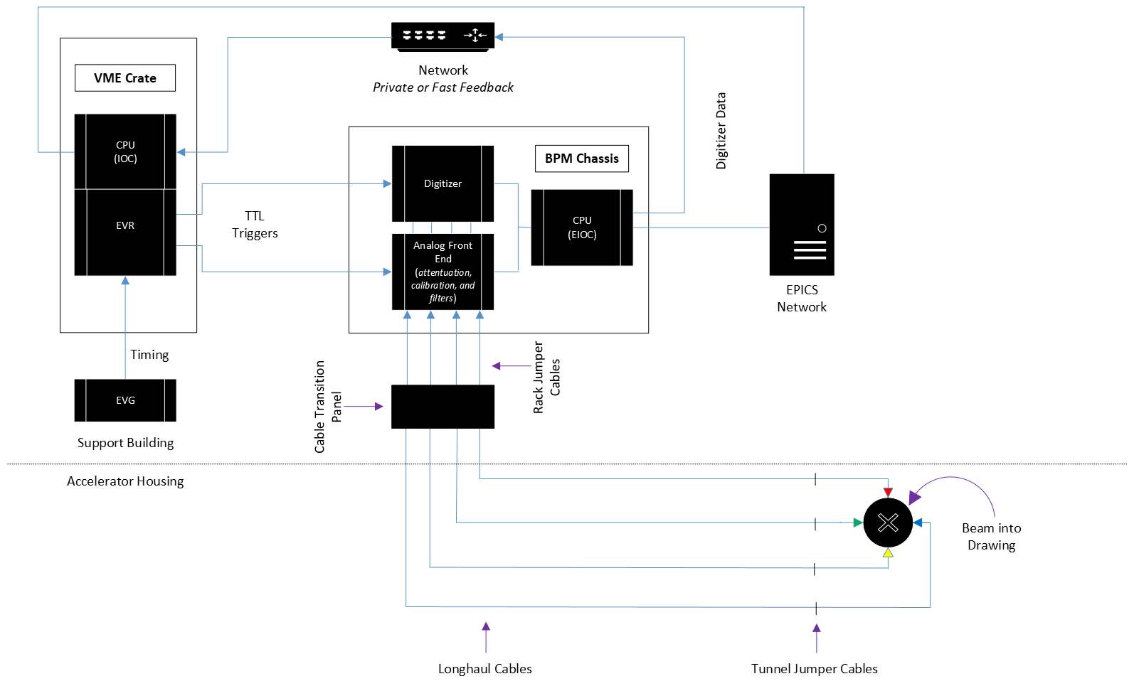
(Figure 1- Setup for VME based BPMs, note that the VME crate sends forward communication to the BPM chassis through the use of TTL triggers. The AFE (Analog Front End) of BPM chassis receives raw beam
data from the BPM living inside the accelerator housing and performs a series of tasks on the data before sending it to the digitizer ( responsible for converting raw waveform data to digital signals) and the EIOC (Embedded IOC) living in side the BPM Chassis)
An Example of a Healthy Stripline BPM
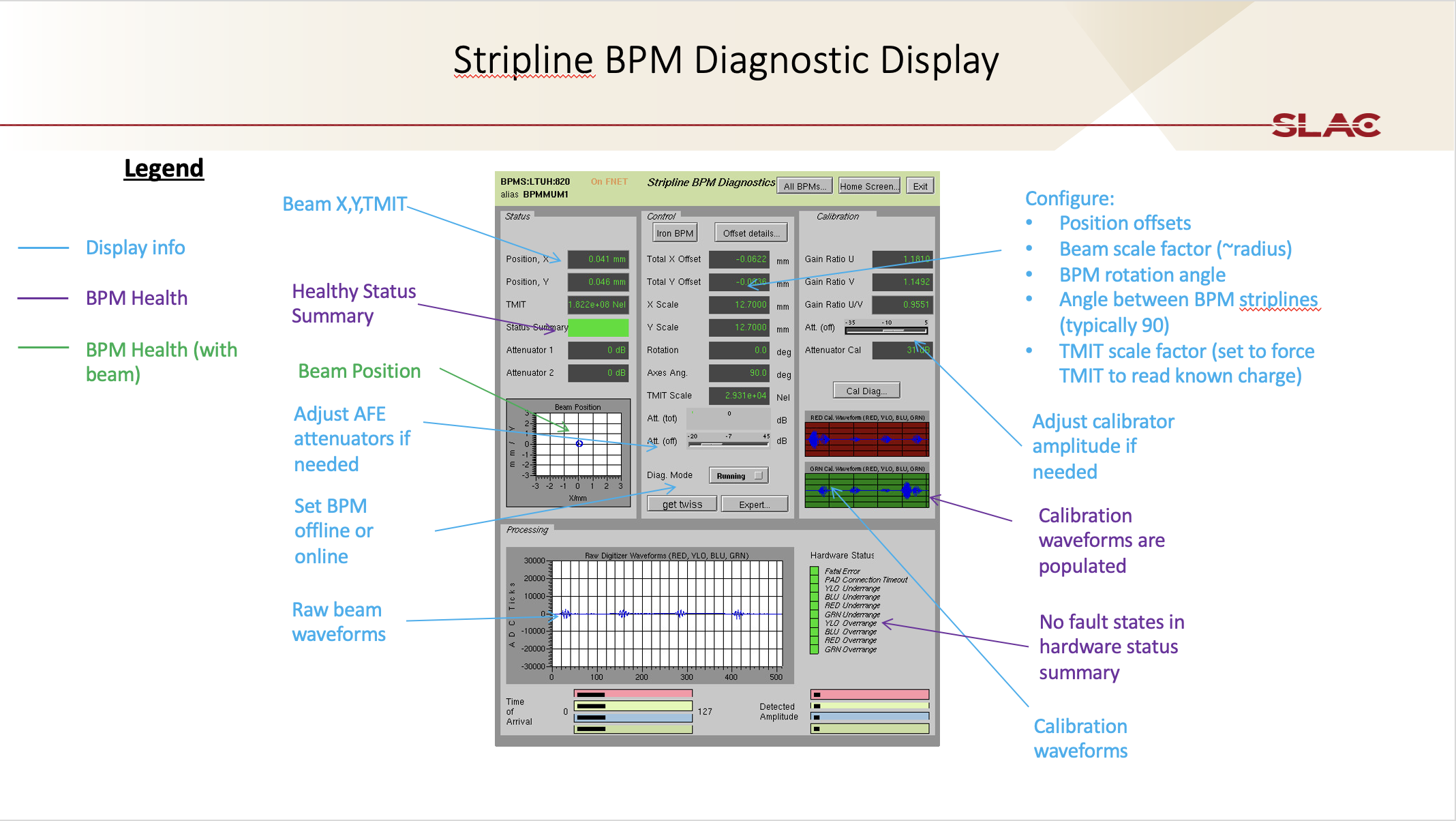
(Figure 2- An example of a healthy Stripline BPM with comments, blue comments in this figure are to provide the user with information about the display itself, purple comments are to provide information on what a healthy BPM can look like when there is no beamrate,
and finally green comments are to provide additional information on what BPM health looks like with beam after reviewing the purple comments.)