Introduction:
The Optoboard System is the data aggregation and signal conversion stage of the ATLAS ITk Pixel data transmission chain. The basic working principle is:
- DATA: 6x 1.28 Gbps electrical links from the front-end modules are serialized into 1x 10.24 Gbps optical link and transmitted to the backend (FELIX).
- CMD: 1x 2.56 Gbps optical link with trigger and command are deserialized into 8x 160 Mbps electrical links and transmitted to the front-end (ITkPix). Also the Optoboard gets controlled through the optical link.
One Optoboard consists of:
- 4 lpGBTv1: one as a master available through IC, three as slaves controlled through I2C controller of the master. Manual/description here.
- 4 GBCR2: all controlled through lpGBT master I2C controller. Manual here.
- 1 VTRx+: controlled through lpGBT master I2C controller. Description here.
- 1 bPOL2V5 carrier board: houses the bPOL2V5 ASIC that converts 2.5 V to 1.2V. Datasheets here.
Specific for SLAC's test-Optopanel will be marked in red .
Mechanics:
- Up to 8x Optoboards are housed in one Optobox. One Optobox consists also of:
- 1 Powerboard: hosts 5 bPOL12V ASICs (conversion 9 V to 2.5 V) and 1 MOPS chip
- 1 Connectorboard: handles power distribution form the 5 bPOL12V to the 8 Optoboards according the SP chain powering/detector layout.
- Up to 28x Optoboxes (14x normal, 14x mirrored) are housed in one Optopanel.
- Each side of the ITk has 4 Optopanels.
Currently specific for SLAC IS demonstrator:
4x Optoboard V2.1 are housed in one Optobox. This Optobox is housed in a Test-Optopanel.
Interfaces:
Please refer to our Interface Document here. All the connectors of the Optoboard System is explained there.
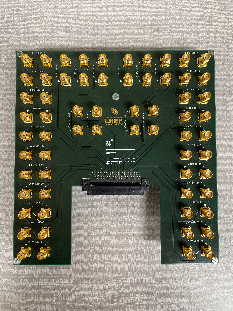
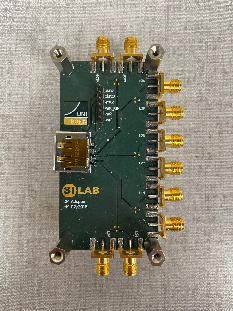
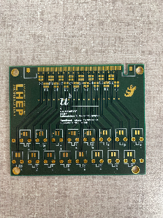
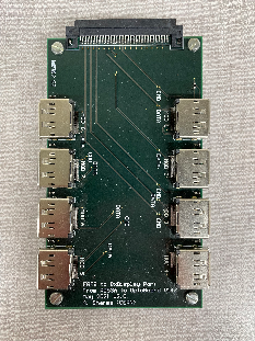
Adapter boards:
| ERF-SMA (routing, schematics) from Bern | DP-SMA (routing, schematics) | ERF-twinax from Bern | ERF-8x DP (routing, schematics) |
|---|---|---|---|
|
|
|
|
Schematics:
All schematics for all of Berns designed PCBs can be found here.
Optoboard system support:
We collect support requests and general questions on our Mattermost channel Bern-Optoboard (invite link). Your contacts as of Aug. 2022 are Aaron O'Neill and Daniele del Santo.
Optoboard software for FELIX:
We created a repository with scripting software to easily configure the Optoboard: https://gitlab.cern.ch/bat/optoboard_felix. A lot is documented in the readme and wiki of the repository.
The repository is located in the directory:
/home/itkpix/optoboard-system
To configure an Optoboard V2.1 with the default configurations found simply run these scripts:
In a first terminal felixcore:
cd /home/itkpix/software    # Jan/2023 ITkPixV1. Previously was felix-sw/flx-sw-2022-08-11
source setup.sh
x86_64-centos7-gcc11-opt/felixcore/felixcore -d 0 --data-interface lo --elinks 0,4,8,12     # starts felixcore, check your links!
Note that the elinks might change according your connectivity scheme. More information from Ismet here.
In a second terminal:
- In case the optoboard setup was done previously and remained powered on, you can proceed with just a simple environmental setup:
cd /home/itkpix/optoboard-system
source flx_opto_setup.sh     # warm start
- In case the optoboard was just powered or got stuck, you need to do a cold start setup (this is incompatible with felixcore so that you need to terminate felixcore in the other window before doing this):
cd /home/itkpix/optoboard-system
source flx_opto_setup_fresh.sh    # cold start
At this point the master link between FELIX and optoboard should be established which you can check using the command
flx-info link
which should typically show something like:
 Link alignment status
------------------------
Channel |  0    1
        ----------
Aligned | YES  NO

Channel |  2    3
        ----------
Aligned | NO   NO
which indicates the master lpGBT link (Channel 0) is established so that further configuration can proceed. The optoboards only have the master lpGBT enabled at powerup while the other lpGBTs will be brought up at the optoboard configuration stage (this requires felixcore up and running):
cd /home/itkpix/optoboard-system/optoboard_felix
python InitOpto.py -optoboard_serial 00000000 -vtrx_v 1.3 -flx_G 0 -flx_d 0 -configure 1
The -optoboard_serial specifies the serial number used (00000000 is the default one for Optoboard V2.1), -flx_G is the link group number of FELIX and -flx_d the FELIX device. The option -configure set to 1 will configure all lpGBTs, if set to 0 will configure only the master. If -optoboard_serial is set to 00000000 and -vtrx_v 1.3, optoboard_felix sends the parameters in the config ~/optoboard_felix/configs/optoboard2_lpgbtv1_gbcr2_vtrxv1_3_default.json to the lpGBTs, GBCR and VTRx+. Check the FELIX documentation or the optoboard_felix readme for more information on this. If this succeeded, the single optoboard LV current will go up to ~900mA.
If you do flx-info link after optoboard configuration you should now see that all links are aligned with YES. If you do flx-info podpower you should see something like this (if single Optoboard outside test-Optopanel is connected then only Chan 0-3 are relevant):
Optical power (Receive=RX or Transmit=TX) of channel in uW:
        |     0   |     1   |     2   |     3   |     4   |     5   |     6   |     7   |     8   |     9   |    10   |    11   |
        |=========|=========|=========|=========|=========|=========|=========|=========|=========|=========|=========|=========|
 1st TX |  983.30 |  986.10 |  892.10 |  970.00 |  937.50 | 1009.70 |  916.20 |  970.30 |  920.00 |  960.80 |  924.40 |  958.50 |
 1st RX |  946.80 |  790.20 |  870.50 |  761.80 |    0.00 |    0.00 |    0.00 |    0.00 |    0.00 |    0.00 |    0.00 |    0.00 |
In case any present link got power below 700uW, please check the VTRX+ fiber pigtail ferrule junction to the MPO splitter is fully plugged in. You can further check the optoboard configuration for link speed, tracking mode and link locking phase by running InitOpto.py with the additional option -i which starts an interactive python session after configuration and defines an opto object that can be probed for various settings (see full API documentation for details):
cd /home/itkpix/optoboard-system/optoboard_felix
python -i InitOpto.py -optoboard_serial 00000000 -vtrx_v 1.3 -flx_G 0 -flx_d 0 -configure 1
>>> opto.bertScan(...) # perform BERT scans
>>> opto.opto_doc() # Print status information on all lpgbts (equivalent to following functions for lpgbt1)
>>> opto.lpgbt1.check_PUSM_status() # check power up state machine state (int 0-19 see ch 8.1 of lpgbt manual, 19=ready)
>>> opto.lpgbt1.check_lpgbt_config_pins() # check hardware configuration
>>> opto.lpgbt1.check_EPRX_status() # check elink uplink status for all channels (enabled, rate, polarity, phase)
>>> opto.lpgbt1.check_EPRX_locking() # check phase locking
After fibre fanout installation:
After the fibre fanout is installed, configuring the Optoboards will look similar to this:
python InitOpto.py -optoboard_serial 00000000 -vtrx_v 1.3 -flx_G 0 -flx_d 0 -configure 1
python InitOpto.py -optoboard_serial 00000000 -vtrx_v 1.3 -flx_G 1 -flx_d 0 -configure 1
python InitOpto.py -optoboard_serial 00000000 -vtrx_v 1.3 -flx_G 2 -flx_d 0 -configure 1
python InitOpto.py -optoboard_serial 00000000 -vtrx_v 1.3 -flx_G 3 -flx_d 0 -configure 1
Or with the separate configs that are created in ~/optoboard_felix/configs:
python InitOpto.py -vtrx_v 1.3 -c /configs/2400003.json
python InitOpto.py -vtrx_v 1.3 -c /configs/2400006.json
python InitOpto.py -vtrx_v 1.3 -c /configs/2400007.json
python InitOpto.py -vtrx_v 1.3 -c /configs/2400011.json
Note that in this case the connected FELIX fibre channel has to be set inside the configuration file as described in the readme here.
In a currently ongoing effort by Bern PhD student Daniele dal Santo, the software will be integrated into the ITk demonstrator software itk-demo-sw.
Further tools:
flpgbtconf: FELIX low level tool to communicate with (and only with) the lpGBT master directly. flpgbtconf -h will give you help on the tool, here an example:
flpgbtconf -1 -I 0x74 -G 0 -d 0 ULDATASOURCE5_DLG0DATASOURCE 0x1 # sets CMD from data to PRBS7 pattern on EPTX00 and EPTX02
-I 0x74 is the address for the lpGBT and the option -1 for the lpGBT version 1. Consult the lpGBT manual for all the various register names. You can also check which version of FELIX firmware we are running with the command:
flpgbtconf -1 -I 0x74 -G 0 -d 0 ROM # Check FELIX firmware version
The stable version for ITkPixV1 readout since DEc/2022 was FLX712-PIXEL-2x2CH-221101-1129-GIT:rm-5.0/2749.
There are many more options with FELIX, consult the FELIX user manual.
Running ITkPixV1 Digital Calibration
Note: all procedures above related to optoboard setup are completely independent of the pixel modules so that they could be done with the pixel module powered off. After the optoboards are fully configured, we could extend the opoeration to the pixel modules. The ITkPixV1.0 SCC is typically powered with 2.0V LV and the initial current of the SCC just after powerup before configuratoin is ~3.07A. With optoboard completely configured, one can power up the module LV then check if the data link are aligned:
flx-config list | grep DECODING_LINK_ALIGNED
for which you7 might see some output like:
0x2180 [R  57:00]                       DECODING_LINK_ALIGNED_00  0x000000030000000  Every bit corresponds to an E-link on one (lp)GBT or FULL-mode
0x2190 [R  57:00]                       DECODING_LINK_ALIGNED_01  0x000000030000000  Every bit corresponds to an E-link on one (lp)GBT or FULL-mode
0x21a0 [R  57:00]                       DECODING_LINK_ALIGNED_02  0x000000000000000  Every bit corresponds to an E-link on one (lp)GBT or FULL-mode
...
where the none zero bit field ('3' in this example) indicated aligned links.
The current version of YARR for ITkPixV1 calibration (still being validated) resides at /home/itkpix/YARR_FELIX/ which is based on branch devel_itkpix_felixNetio.
cd /home/itkpix/optoboard-system
source flx_opto_setup.sh

cd /home/itkpix/YARRdev/Yarr_itkpix/
source ../setup.sh
source config_CalTrigSeq.sh 3 0  #arg1 is scantype 3=digitalB; arg2 is FELIX device No.
source run_rd53b.sh
During the startup of the digital calibration, the module configuration would increase the ITkPixV1.0 SCC current to 4.38A (from, 3.07A). The calibration results are kept at /home/itkpix/YARR-FELIX/data/. Successful calibration should have an output Root file.
Test-Optopanel at SLAC:
The test-Optopanel houses one Optobox with 4 Optoboards. It has a twinax inlet (round) and a fibre outlet (rectangle). The Optobox is mounted on a cooling plate with two 8 mm pipes.
A collection of photographs from the test-Optopanel and its sister at CERN SR1 can be found here. See also this Twiki here of the SR1 test-Optopanel which has similiar information (but some very different configurations).
Optoboards:
| slot: | OB1 | OB2 | OB3 | OB4 | OB5 | OB6 | OB7 | OB8 |
|---|---|---|---|---|---|---|---|---|
| serial: | 2400006 | - | 2400003 | - | 2400007 | - | 2400011 | - |
| powering from bPOL: | A | A | B | B | C | C | D | D |
| idle current* [mA] | 182 | - | 165 | - | 168 | - | 174 | - |
| FELIX link: | ||||||||
| Current Location | SLAC | ANL | OSU | SLAC |
*after power-up and inside the test-Optopanel with 9.0 V supplied. If powered outside the test-Optopanel directly on the connector with 2.5 V expect a current ~415 mA.
| History | Comments |
|---|---|
| 2400011 | Resistor R108 removed Oct/2022 to debug FELIX FEC12 mode problem. R108 back on Feb/2023. |
Connectors:
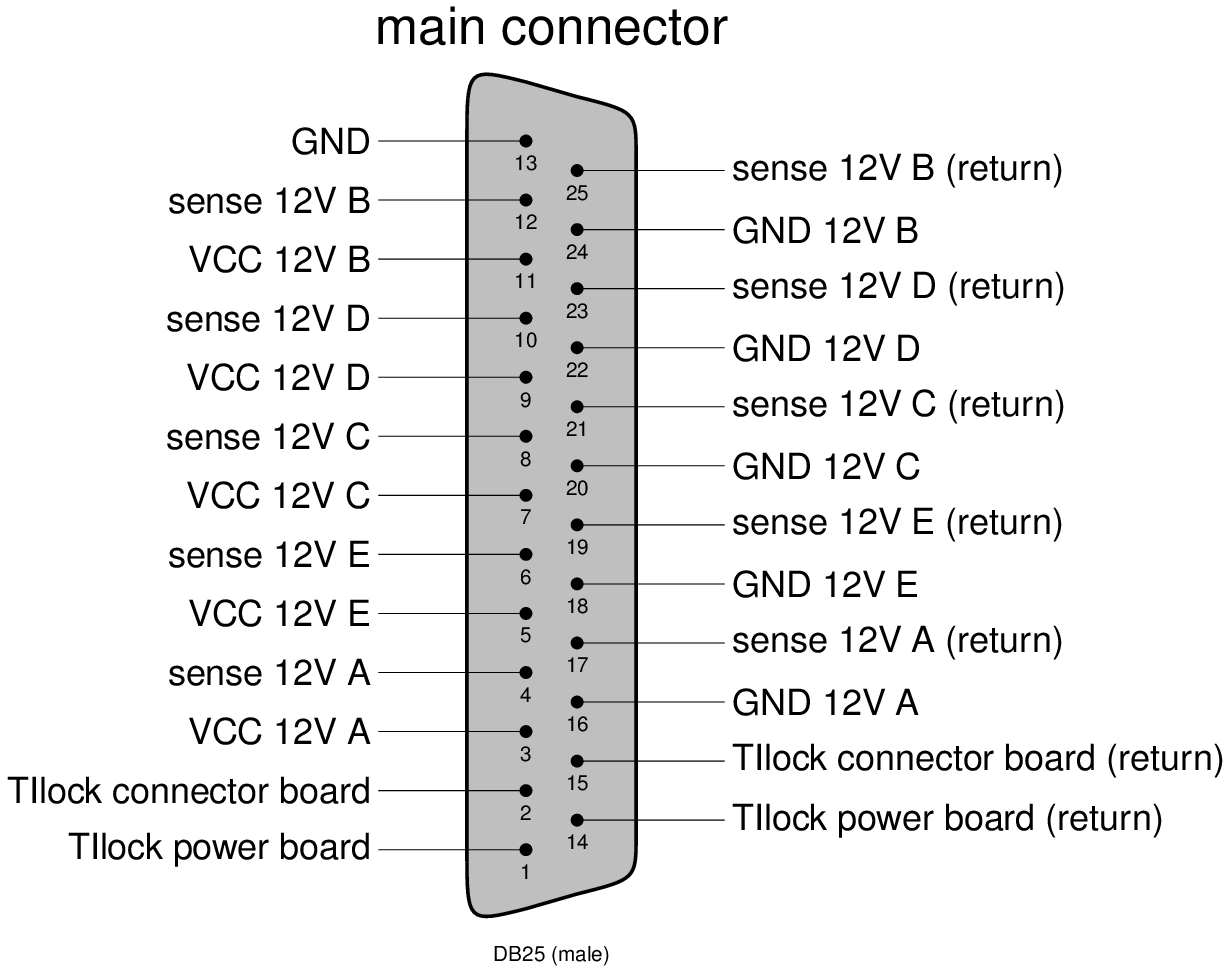
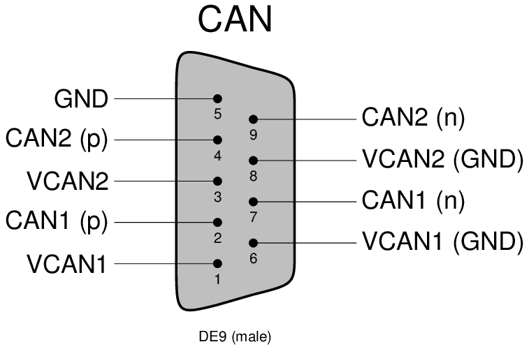
Check the above interfaces document for more detailled description.
Banana plugs are labelled according to powered bPOL12V.
Cooling and dry air inlet/outlet: FESTO 8 mm
DCS:
Currently no MOPS is mounted on the Powerboard inside the test-Optopanel (due to availability). We will ship one as soon as we got our hands on them.
SLAC Single Optoboard Test Setup
The initial single optoboard setup used for the early SLAC tests with single chip cards is summarized in the diagram below:
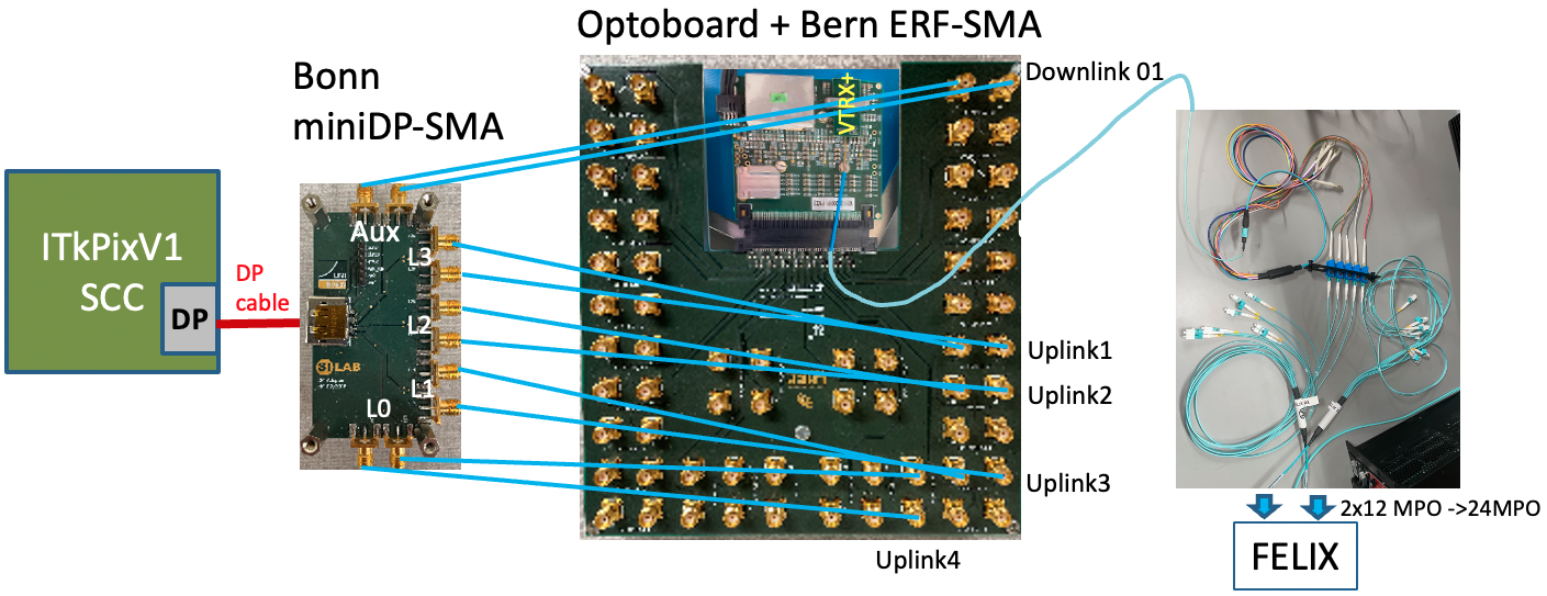
| Bonn miniDP-SMA | Bern ERF-SMA | lpGBT |
|---|---|---|
| AUX | DOWNLINK 01 | 1 |
| LN3 | L1 UPLINK 01 | 1 |
| LN2 | L1 UPLINK 02 | 1 |
| LN1 | L1 UPLINK 03 | 1 |
| LN0 | L1 UPLINK 04 | 1 |
Each fiber in the pigtail corresponds to data coming from a separate lpGBT (verification needed for RX 3 and 4):
| lpGBT | VTRX+ fiber | FELIX fiber |
|---|---|---|
| 1 | red (7) | TX 1 |
| 1 | white (6) | RX 1 |
| 2 | slate (5) | RX 2 |
| 3 | brown (4) | RX 3 |
| 4 | green (3) | RX 4 |
Note that the Optoboard VTRX+ fiber pigtail MT ferrules connection to MPO12-LC fiber splitter is a simple slip on which requires careful manual recognition of right polarity (see ITkPixV1 readout page) which can easily slip off but prevents accidental large force breaking the fiber. It is advisable to always check the link light level with flx-info podpower to verify the fiber link is healthy (>700uW). How the VTRX+ fiber pigtail lines are structured is described in the Optosystem Interface document AT2-IP-GM-0010 (Table 4) with 5 out of 12 fibers active per optoboard. How the FELIX MPO24 port is structured and fanout with MPO24->2xMPO12→LC splitters are described in the FELIX readout and Direct FELIX confluence pages.
Current firmware allows only 2 lpGBTs to be readout, such that the link alignment string is fixed to x0000000300000000 for channels 00 and 01 in unaligned state. Alignment can be checked using data from module RX 0 (L0 on miniDP-SMA) after module configuration, giving the following link alignment strings independently of which e-links are subscribed on felixcore startup:
| miniDP-SMA Channel | Alignment String Name | Value |
|---|---|---|
| L1 UPLINK 00 | DECODING_LINK_ALIGNED_00 | 0x000000030000001 |
| L1 UPLINK 01 | DECODING_LINK_ALIGNED_00 | 0x000000030000010 |
| L1 UPLINK 02 | DECODING_LINK_ALIGNED_00 | 0x000000030000000 |
| L1 UPLINK 03 | DECODING_LINK_ALIGNED_00 | 0x000000030001000 |
| L1 UPLINK 04 | DECODING_LINK_ALIGNED_00 | 0x000000030010000 |
| L1 UPLINK 05 | DECODING_LINK_ALIGNED_00 | 0x000000030100000 |
| L2 UPLINK 06 | DECODING_LINK_ALIGNED_01 | 0x000000030000001 |
| L2 UPLINK 07 | DECODING_LINK_ALIGNED_01 | 0x000000030000010 |
| L2 UPLINK 08 | DECODING_LINK_ALIGNED_01 | 0x000000030000000 |
| L2 UPLINK 09 | DECODING_LINK_ALIGNED_01 | 0x000000030001000 |
| L2 UPLINK 10 | DECODING_LINK_ALIGNED_01 | 0x000000030010000 |
| L2 UPLINK 11 | DECODING_LINK_ALIGNED_01 | 0x000000030100000 |
There is a broken connection in L1 UPLINK 02 in the ERF-SMA board or within the optoboard itself. Note that alignment is sensitive to polarity of TX connection (i.e. NP↔NP vs NP↔PN) but not to the RX connections.
Some Useful Links
- Optoboard System Documentation
- FELIX JIRA (Oct/22) on optoboard + ITkPix readout setup
- CERN mattermost Bern-Optoboard channel
- Talk (Dec/9/2022) by Angira Rastogi on Optoboard-FELIX setup at LBNL