Outline
- Ring Loading Tooling, 19-1 RD53a
- Handling Frame, 19-1 RD53a OB Stave
- Shipping Box, 19-1 RD53a OB Stave
- Stave Loading Tooling, 19-1 RD53a OB Stave
- Stave Loading Tooling, 19-1 RD53a IB Stave
Ring Loading Tooling
Ring loading glue locations drawing (not released): REF-000160474 (LOADING FIXTURE, 19-1 RING).pdf
Ring Loading Tooling Drawings and .step files:
- 19-1 Ring.zip
- In the future, plan to review drawings in Mechanics meeting and release/add to Windchill CAD library, to reduce risk of interface issues.

Handling Frame and Shipping Box
Drawings (not released): REF-000202479 (SHIPPING AND STORAGE FIXTURE, OB STAVE, 19-1) CHECKPRINT 14FEB2022.zip
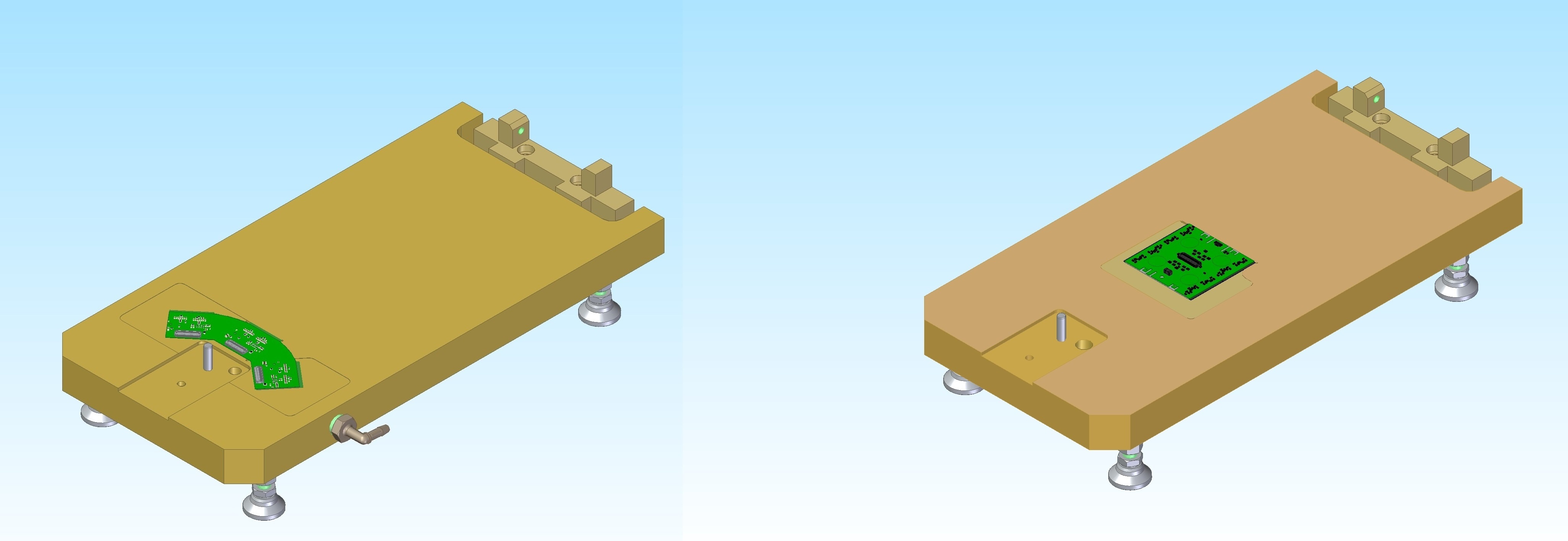
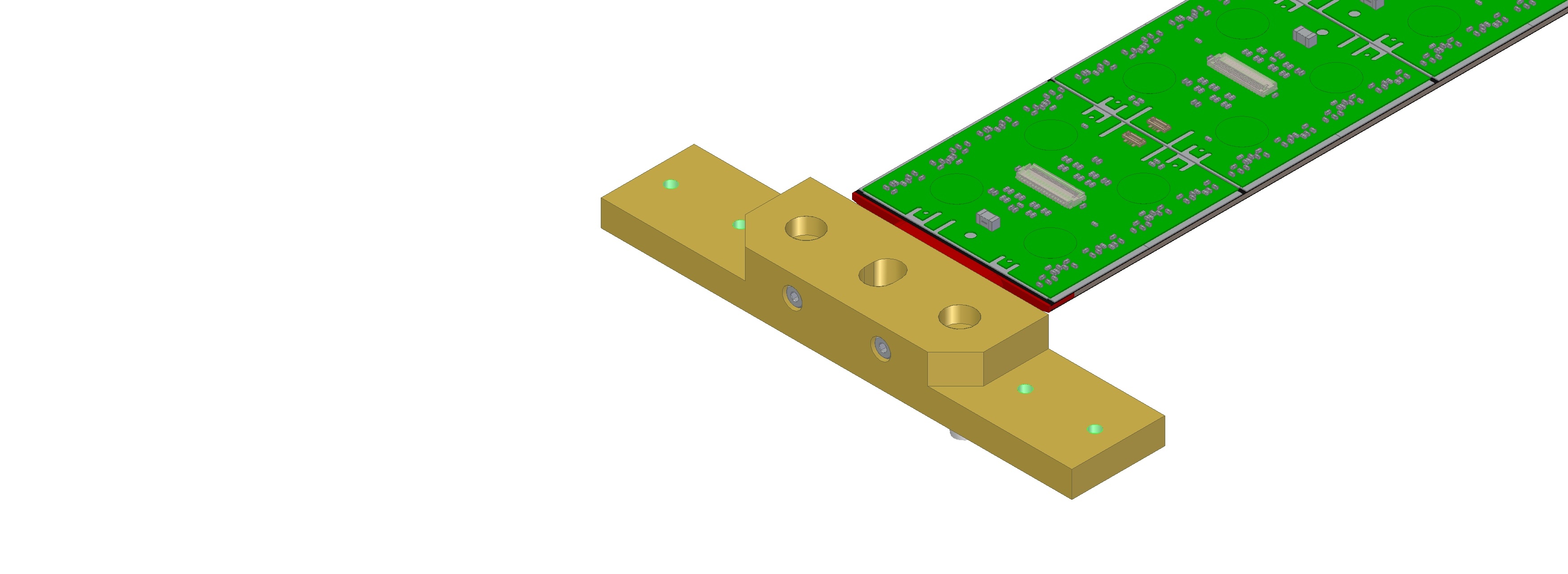
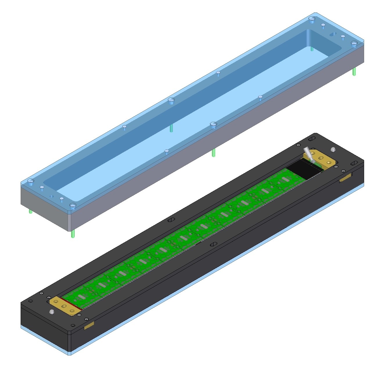
Handling Frame with 19-1 OB Stave:
Interface block to join Stave and Handling Frame (drawing not released):

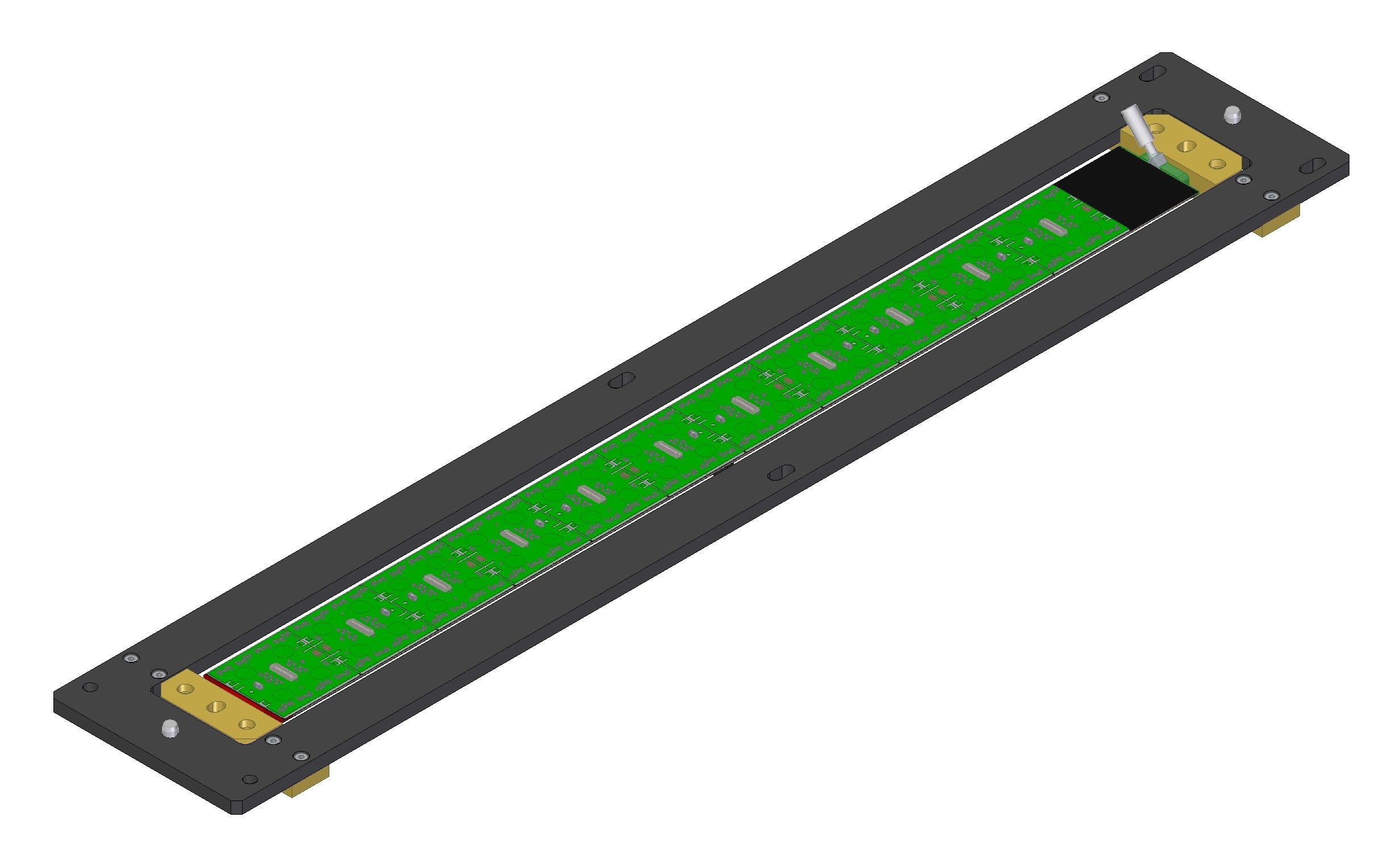
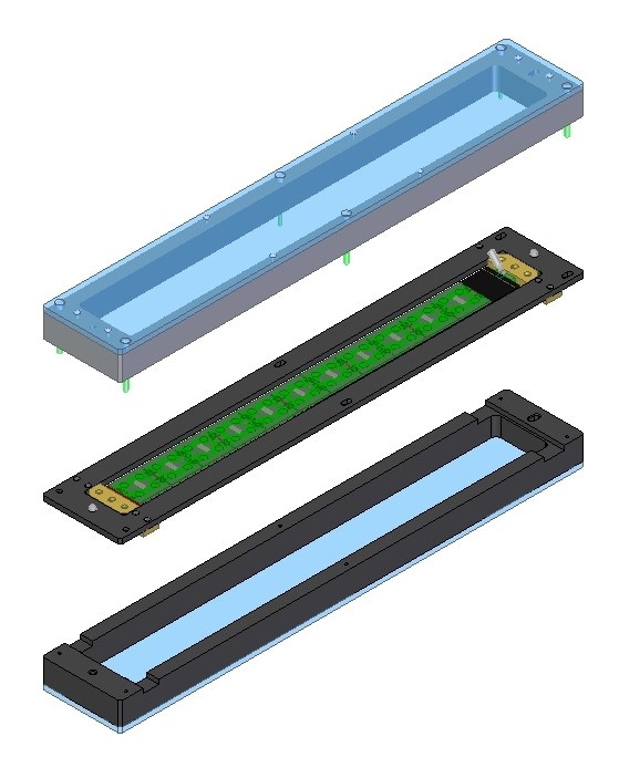
Shipping Box:

Stave Loading Tooling, 19-1 OB Stave
Version 2, revised, Stave Loading Tooling drawing drafts (not released):
- Top Level Assembly: REF-000202041 (LOADING FIXTURE ASSY, 19-1 OB STAVE).pdf
- Baseplate: REF-000203575 (BASEPLATE AND PINS, LOADING FIXTURE, OB STAVE, 19-1, V2).pdf
- Loading Bridge: REF-000202287 (LOADING BRIDGE, FIXTURE, 19-1 OB STAVE).pdf
- Covers for loaded modules: REF-000202337 (COVER SECTION, 19-1 OB STAVE).pdf
- Pickup table assy: REF-000202485 (PICK UP TABLE, QUAD, 19-1 OB STAVE LOADING FIXTURE).pdf
Some draft prints sent to quote:
| Items | Vendor | Date | Response |
|---|---|---|---|
| GoProto | 3/3/2022 | Working on quote |
| SLAC machine shop | 3/4/2022 | |
| KAL Machining | 3/7/2022 | |
| Parametric USA | 3/7/2022 | Quote: PQ104809.pdf $8k, 4-5 week lead |
| Pro-Tek Manufacturing | 3/7/2022 | Received |
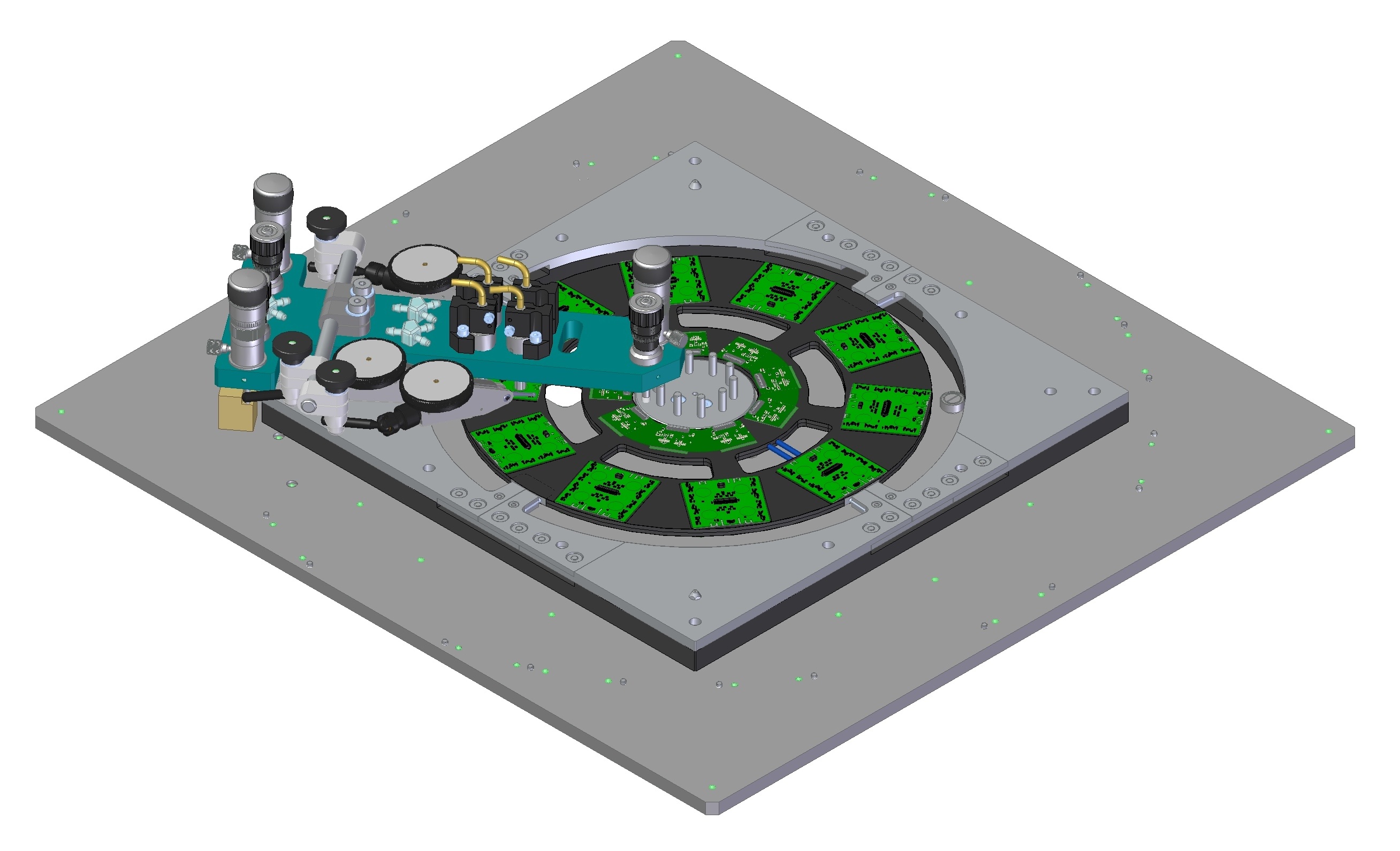
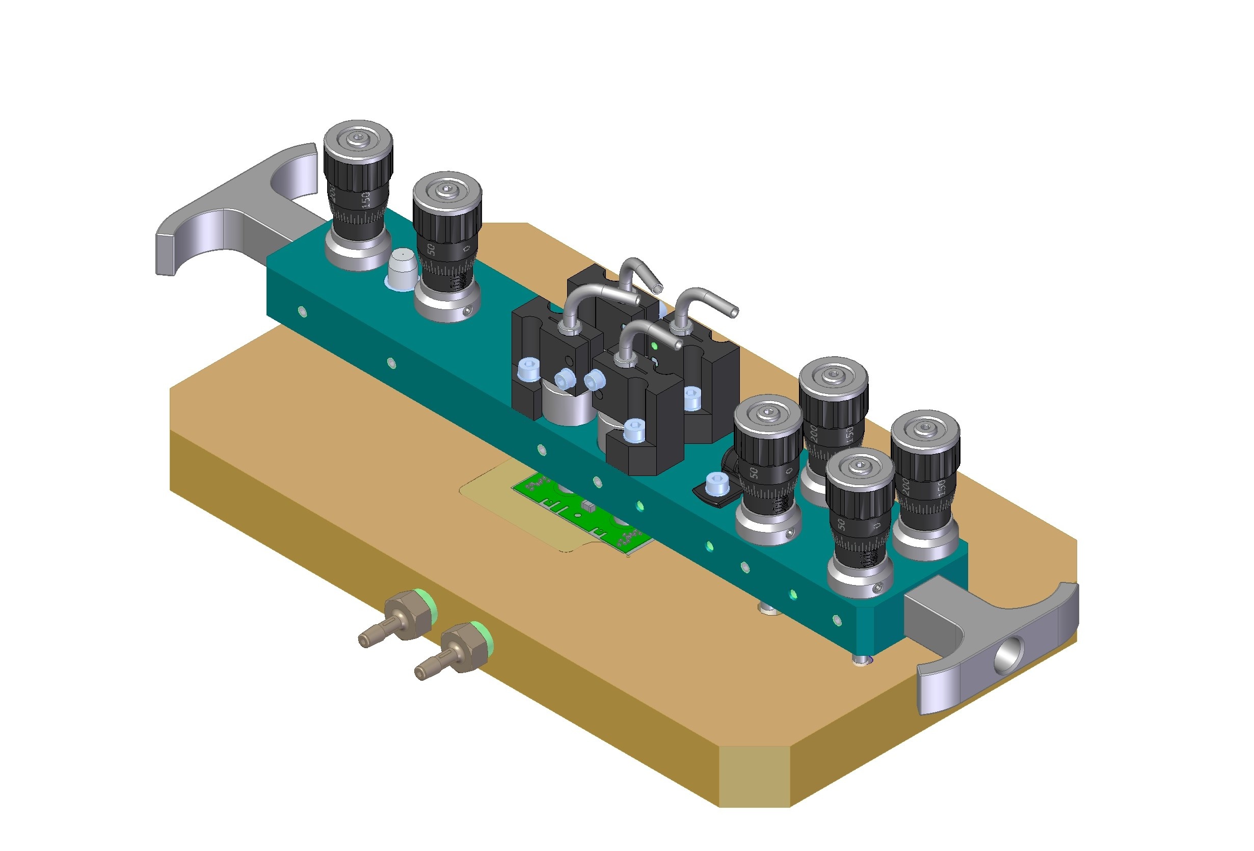
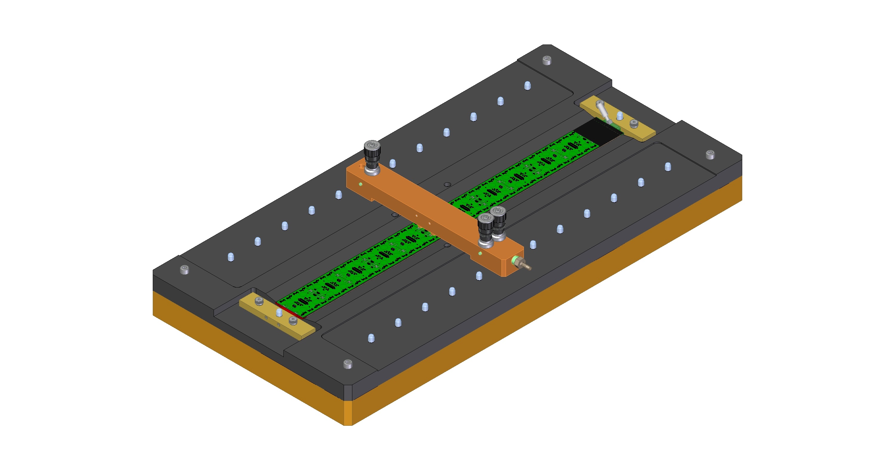
Loading Tooling, OB Stave:

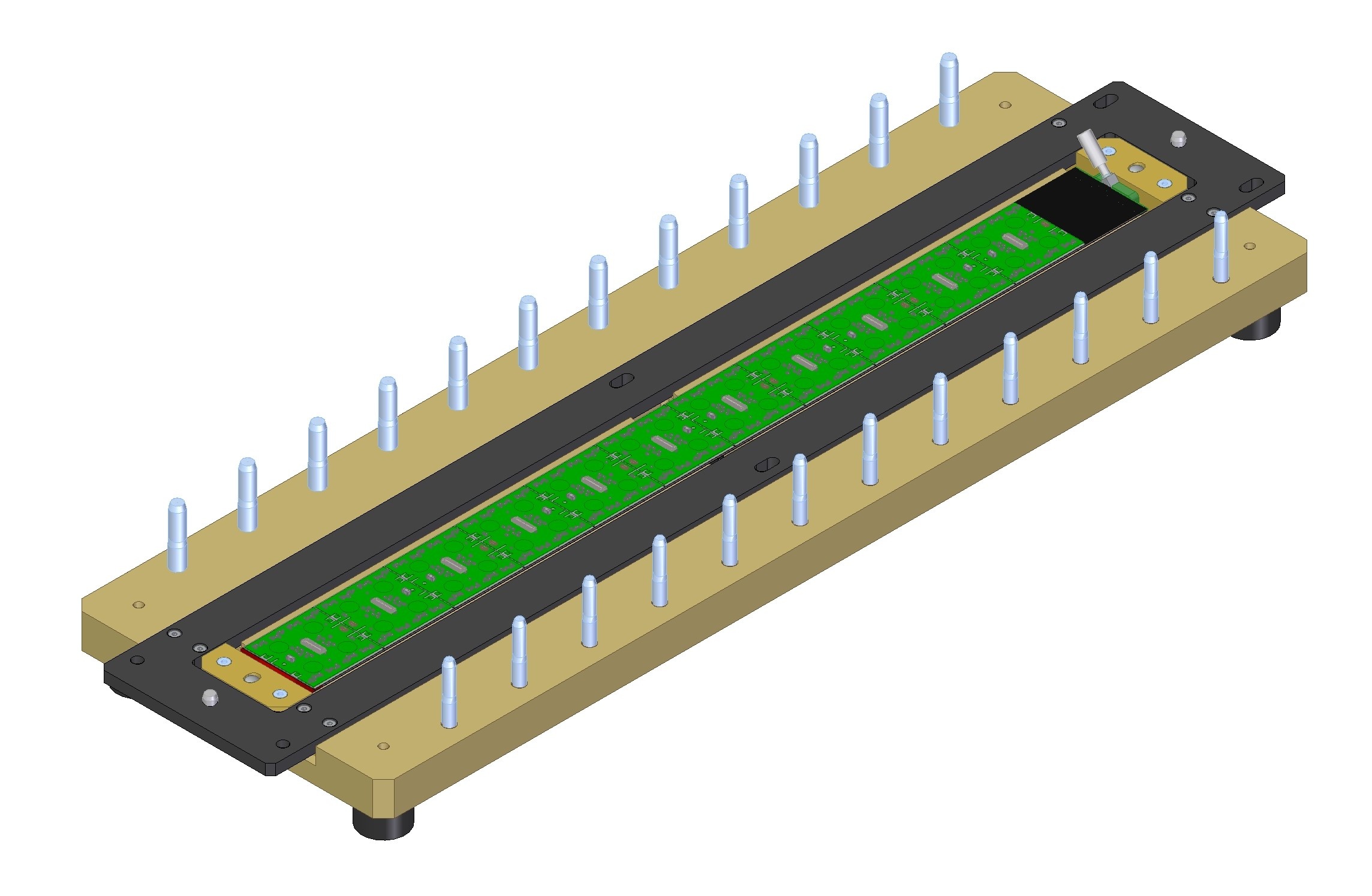

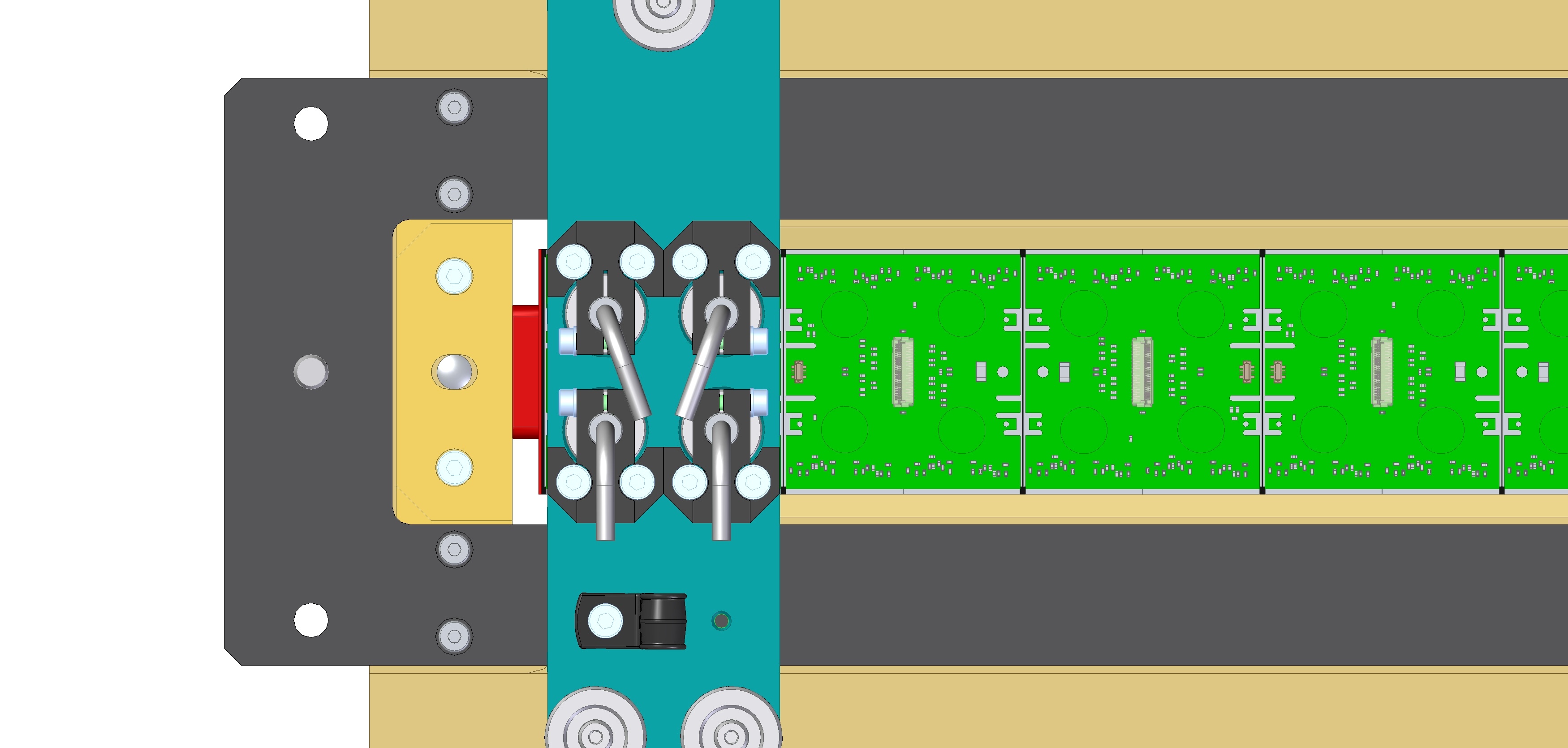

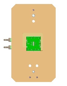
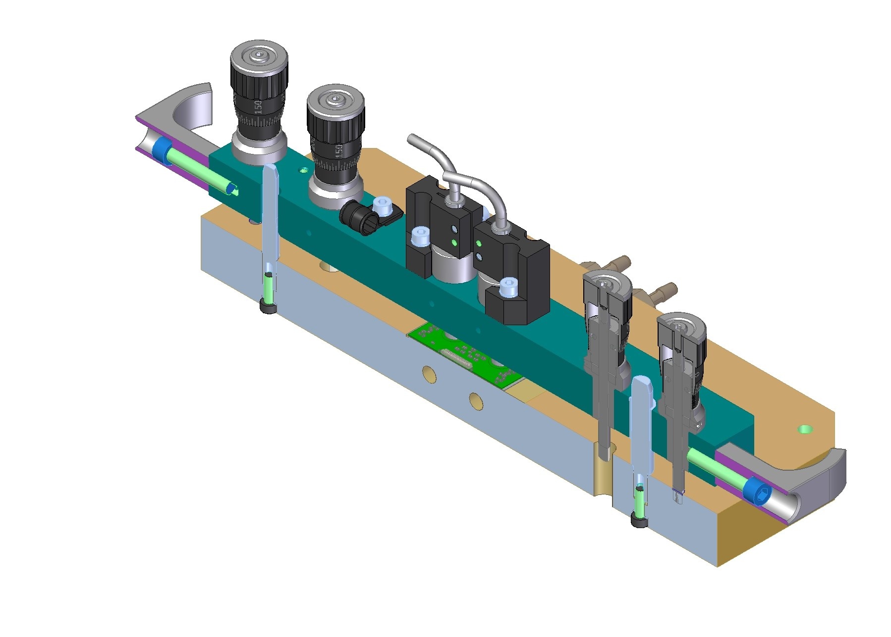
Section view:
Summary of requirements for loading 19-1 Outer Barrel Stave:
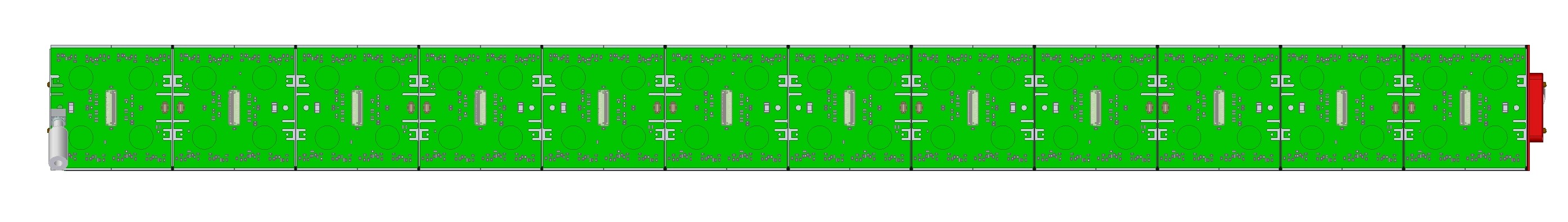
- Load RD53a Quad modules (drawings: 150um, 400um) with connectors oriented as shown in picture above
- Load modules onto 19-1 OB Stave (no drawing yet, preliminary CAD on LBL Windchill site)
- Load without collisions: 200um nominal gap / 100 micron minimum gap between modules (no assembly drawing yet showing modules on stave)
- Glue layer thickness to be 100um -50/+100um
- ESD protection during loading: grounding of tooling
- Mechanical protection of wire bonds during loading: stay clear of wire bonds, handle modules using tooling only, consider covers/shields
- Baseplate to be installed onto glue robot: weight limit 7kg (per manual)
- Stave to be removed from baseplate and transferred to test box for QC testing
Summary of specifications:
- Closely toleranced pins/bushings – same approach as used for 19-0 tooling
- Requirement: +/-75um module position tolerance in local support coordinate system (per requirements document "ITk Pixel Module Loading Accuracy Requirements" AT2-IP-ES-006-v3)
- Distribute tolerances:
- +/-50um module position relative to loading tooling baseplate coordinate system (to avoid collisions with 100um gap between modules).
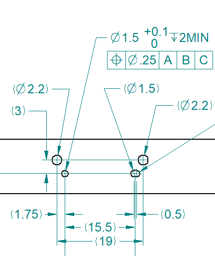
- Dowel pins in baseplate – two per module location.
- Bridge to have bushing and slot for precision fit onto dowel pins.
- +/-25um local support position relative to loading tooling baseplate coordinate system (to accurately place modules to meet +/-75um requirement).
- Dowel pin in baseplate – to accurately locate one end of the Stave in Z.
- Tooling to fasten to mounting features on ends of Stave.
- +/-50um module position relative to loading tooling baseplate coordinate system (to avoid collisions with 100um gap between modules).
- Glue with beads to control glue layer thickness
- 100um dia beads, for ~75um glue layer thickness on carbon fiber.
- Loading tooling does NOT control the glue layer thickness.
- Loading bridge to rest on the module's pickup areas (vacuum pad locations) during gluing.
- Loading bridge to have micrometer adjusters to level the tool relative to the baseplate – to apply pressure at all vacuum pad locations during gluing.
- Loading bridge to have micrometer adjusters to level the tool relative to the pickup table – to make good contact between vacuum pads and module.
- Vacuum pads to pick up modules
- Vacuum pads to fit within clear areas on modules.
- Height adjustment of vacuum pads while on pickup table.
- Vacuum to securely hold modules.
- Tolerances:
- Module position relative to loading tooling baseplate (need +/-.050mm):
- Baseplate has:
- Dowel pin, stepped, 6mm OD, h7 tolerance. (Misumi SWPG6-P6-Q5.5-L12-B12-E3-F15)
- Dowel pin, stepped, 8mm OD, h7 tolerance. (Misumi HWPG6-P8-Q7.5-L11-B12-E3-F15)
- Loading bridge has:
- Bushing, 8mm ID, G6 tolerance. (Misumi JBAUN8-20)
- Machined slot, 6mm internal width, G6 tolerance.
- Baseplate has:
- Module position relative to loading tooling baseplate (need +/-.050mm):
| Tolerance Item | Where Used | Tolerance (mm, Dia.) |
Pick-up Table Edge Repeatability (for successive modules) | Locating Module to Pickup Table | .012 |
| Bridge Bushing ID | Locating Loading Bridge to Pick-up Table | .012 |
| Pick-up Table Pin OD | Locating Loading Bridge to Pick-up Table | .012 |
| Pin Location | Locating Loading Bridge to Pick-up Table | .020 |
| Bridge Bushing ID | Locating Loading Bridge to Loading Fixture | .012 |
| Baseplate Pin OD | Locating Loading Bridge to Loading Fixture | .012 |
| Pin Location | Locating Loading Bridge to Loading Fixture | .020 |
Total: | .100mm (+/-.050mm) | |
| Root Sum Square: | .039mm (+/-.019mm) |
- Stave position relative to loading tooling baseplate (need +/-.025mm):
| Tolerance Item | Where Used | Tolerance (mm, Dia.) |
| Pin Location | Locating Stave to Baseplate | .025 |
Pick-up Table Edge Accuracy (absolute position) | Locating Module to Pick-up Table *choose loading tooling baseplate coordinate system to line up with 1st module *this item affects all modules equally so does not affect gap/distance between modules | .025 |
Total: | .050mm (+/-.025mm) |
- Total for all:
- Limit: +/-.075mm
- Root sum square: +/-.026mm
A design/drawings were made in 2020 (Version 1, deprecated, not released):
- 19-1 STAVE LOADING TOOLING DRAWINGS 15DEC2020.pdf
- V1 does not include lessons learned more recently.
- Deprecated V1 design:
- Changes for V2: add 2nd set of adjusters, stepped pins, adjustable vacuum pads, handles.
Some past presentations:
- 30 March 2021: Tooling and Plans for Loading, 19-0/1, Stave and Ring
Module and Stave dimensions
Compare:
- Module width (ensure all fit on Stave)
- Module FE chip dimensions (re-use tooling)
| Module | FE Chips Dimensions (mm) | Width (mm) | Reference |
|---|---|---|---|
| RD53a Quad 150um | 42.137 x 40.335 | 41.1 | |
| ITkPixV1 150um | 42.2 x 40.3 | 41.1 | |
| ITkPixV1 100um | 42.2 x 40.3 | 40.7 | |
| RD53a Linear Triplet | 61.29 |
Can load up to 11 (of 12) modules onto 19-1 Stave prototype:
- Stave length (flat region): 491.6mm
- RD53a (19-1)
- Modules length: 12*(41.1mm+.2mm)=495.6mm
- 12 modules would result in 4mm overhang beyond end of stave. Plan not to load full stave anyway due to module availability.
- ITkPixV1 100um
- Modules length: 12*(40.7mm+.2mm)=490.8mm
- Appears to fit onto Stave. Module pitch (40.9mm) different from 19-1 pitch (41.3mm) so would need to make a new baseplate with this pitch.
- RD53a Triplet (19-1)
- Modules length: 8*(61.29mm+.15mm)=491.52mm
- Appears to fit onto Stave.
Stave Loading Tooling, 19-1 IB Stave
Requirements - see OB Stave requirements above.
Summary of different requirements for loading 19-1 Inner Barrel Stave:
- Load Triplet modules (drawing, .step)
- Load onto 19-1 IB Stave (no drawing yet, preliminary CAD on LBL Windchill site)
- Load without collisions: 200um nominal gap / 100 micron minimum gap between modules (no assembly drawing yet showing modules on stave)