Content
Motivation
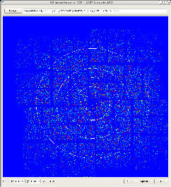
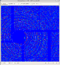
Composite detectors, consisting of many sensors need in alignment. As it is mentioned in CSPAD Alignment optical measurements set sensor positions in quads, but relative quad positions need to be aligned using images. This tool allows to manipulate with geometry parameters (see Detector Geometry) and have a visual control on variation of image. This approach allows to set detector component positions with precision about pixel size.
Alignment tool components
Main control window
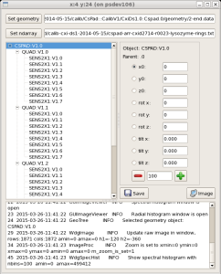
has panels to interact with this application;
- file name for geometry parameters,
- file name for ndarray with image,
- select geometry object component which needs to be aligned (translated and rotated),
- select the parameter which is going to be changed,
- set the step value for parameter variation,
- change the parameter clicking on "+" or "-" buttons,
- save the modified geometry in the file,
- messaging panel.
Image viewer
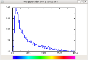
Spectral histogram
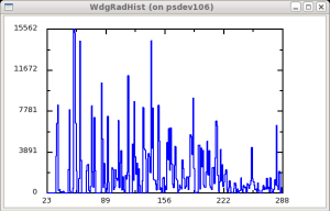
Radial histogram
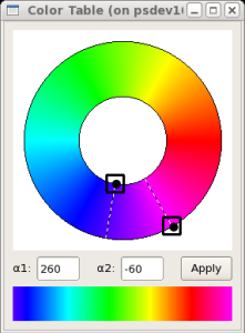
Color table selection widget
Get and run latest version
Code of this tool resides in the package PSQt. If it is not in the release directory, then do these commands:
ssh psana
kinit
cd <one-of-your-directories>
newrel ana-current test_release_directory
cd test_release_directory
sit_setup
addpkg PSQt HEAD
addpkg <other-package-name> HEAD
scons
Hint on input parameters can bee seen by command:
geo -h
...
Usage: geo [-g <geo-fname>] [-i <image-array-fname>] [-L <logger-level>] [-h] [<test-number>]
where optional arguments
-g <geo-fname>- file name with geometry parameters,-i <image-array-fname>- file name with image ndarray,-L <logger-level>- verbosity level, which can beDEBUG, INFO, WARNING, CRITICAL, ERROR,orNONE,-h- show help on input parameters,
and non-optional argument <test-number> is used for debugging purpose.
Application can be launched without parameters by the command
geo
References
Overview
Content Tools