...
Currently specific for SLAC IS demonstrator:
4x 2x Optoboard V2.1 are housed in one Optobox. We have 1 v4 optoboard. This Optobox is housed in a Test-Optopanel.
Interfaces:
Please refer to our Interface Document here. All the connectors of the Optoboard System is explained there.
Adapter boards:
We have 2 FELIX servers in B84 EPP lab, felix (running Centos7) and felix2 (running Alma Linux). The felix server has older versions of the optoboard software, whereas felix2 is brought up with the latest software and firmware releases. felix2 has to be cold rebooted, warm reboot will hang. The issue may be due to ethernet port being shared between the host and IPMI board.
Interfaces:
Please refer to the Bern Interface Document here. All the QC connectors of the Optoboard System is explained there.
Adapter boards:
| ERF-SMA (routing, ERF-SMA (routing, schematics) from Bern | DP-SMA (routing, schematics) | ERF-twinax from Bern | ERF-8x DP (routing, schematics) |
|---|---|---|---|
|
|
|
|
...
Optoboard system support:
We collect Bern collects support requests and general questions on our Mattermost channel Bern-Optoboard (invite link). Your contacts as of Aug. 2022 are Aaron O'Neill and Daniele del Santo.
Optoboard software for FELIX:
We created a repository with scripting software to easily configure the Optoboard: https://gitlab.cern.ch/bat/optoboard_felix. A lot is documented in the readme and wiki of the repository.
The repository is located in the directory:
/home/itkpix/optoboard-system
To configure an Optoboard V2.1 with the default configurations found simply run these scripts:
In a first terminal felixcore:
| Code Block |
|---|
cd /home/itkpix/software    # Jan/2023 ITkPixV1. Previously was felix-sw/flx-sw-2022-08-11
source setup.sh
x86_64-centos7-gcc11-opt/felixcore/felixcore -d 0 --data-interface lo --elinks 0,4,8,12 # starts felixcore, check your links! |
Note that the elinks might change according your connectivity scheme. More information from Ismet here.
In a second terminal:
...
FELIX, optoboard software, and YARR setup:
FELIX firmware (see atlas-project-felix.web.cern.ch for more information):
- felix: firmware version 2221, recommended by Sasha on July 26, 2024 (CERNbox link)
- felix2: there are a few versions of the firmware that can be used:
- Release from Ricardo Luz' March ITk week presentation
- A nightly after ae8a2460of master, pipeline ran on April 24 (build link)
- The testing bitfile directly from Ricardo
FELIX software:
- felix:
- felix2: software git commit 73d2d72a of master (compatible with the latest firmware). Note that for local compilation you need to use
source cmake_tdaq/bin/setup.sh x86_64-el9-gcc13-opt.
Microservices software for optoboard, developed by Bern: https://gitlab.cern.ch/bat/optoboard_felix. A lot is documented in the readme and wiki of the repository.
- felix: optoboard_FELIX
- felix2: same as above, tag 1.0.37
YARR (see Angira Rastogi's March ITk week presentation and LBL documentation):
- felix: v1.5.0, used primarily felixcore
- felix2: v1.5.1, using felix-star
Instructions for felix server:
In a first terminal felixcore:
| Code Block |
|---|
cd /home/itkpix/optoboard-system source flx_opto_setup.sh # warm start felix-sw/felix-distribution # Jan/2023 ITkPixV1. Previously was felix-sw/flx-sw-2022-08-11 source setup.sh x86_64-centos7-gcc11-opt/felixcore/felixcore -d 0 --data-interface lo --elinks 0,4,8,12 # starts felixcore, check your links! |
Note that the elinks might change according your connectivity scheme. More information from Ismet here.
In a second terminal:
- In case the optoboard setup was done previously and remained powered on, you can proceed with just a simple environmental setup: In case the optoboard was just powered or got stuck, you need to do a cold start setup (this is incompatible with felixcore so that you need to terminate felixcore in the other window before doing this):
| Code Block |
|---|
cd /home/itkpix/optoboard-system source flx_opto_setup_fresh.sh # coldwarm start |
At this point the master link between FELIX and optoboard should be established which you can check using the command
| Code Block |
|---|
flx-info link
|
which should typically show something like:
export PYTHONPATH="/home/itkpix/optoboard-system/optoboard_felix_2023Nov/src/:${PYTHONPATH}" # Needed in newer versions of optoboard software |
- In case the optoboard was just powered or got stuck, you need to do a cold start setup (this is incompatible with felixcore so that you need to terminate felixcore in the other window before doing this):
| Code Block |
|---|
cd /home/itkpix/optoboard-system
source flx_opto_setup_fresh.sh    # cold start
|
At this point the master link between FELIX and optoboard should be established which you can check using the command
| Code Block |
|---|
flx-info link
|
which should typically show something like:
| Code Block |
|---|
 Link alignment status
-------------- |
| Code Block |
Link alignment status ------------------------ Channel | 0 1 ---------- Aligned | YES NO Channel | 20 31 ---------- Aligned | YES NO Channel | 2 3 ---------- Aligned | NO NO |
which indicates the master lpGBT link (Channel 0) is established so that further configuration can proceed. The optoboards only have the master lpGBT enabled at powerup while the other lpGBTs will be brought up at the optoboard configuration stage (this requires felixcore up and running):
...
| slot: | OB1 | OB2 | OB3 | OB4 | OB5 | OB6 | OB7 | OB8 | V4 |
|---|---|---|---|---|---|---|---|---|---|
| serial: | 2400006 | - | 2400003 | - | 2400007 | - | 2400011 | - | 4400069 |
| powering from bPOL: | A | A | B | B | C | C | D | D | |
| idle current* [mA] | 182 | - | 165 | - | 168 | - | 174 | - | |
| FELIX link: | |||||||||
| Current Location | SLAC | ANL | OSU | SLAC | SLAC |
*after power-up and inside the test-Optopanel with 9.0 V supplied. If powered outside the test-Optopanel directly on the connector with 2.5 V expect a current ~415 mA.
| History | Date | Comments |
|---|---|---|
| 2400011 | Oct/22-Feb/23 | Resistor R108 removed Oct/2022 to debug FELIX FEC12 mode problem. R108 back on Feb/2023. |
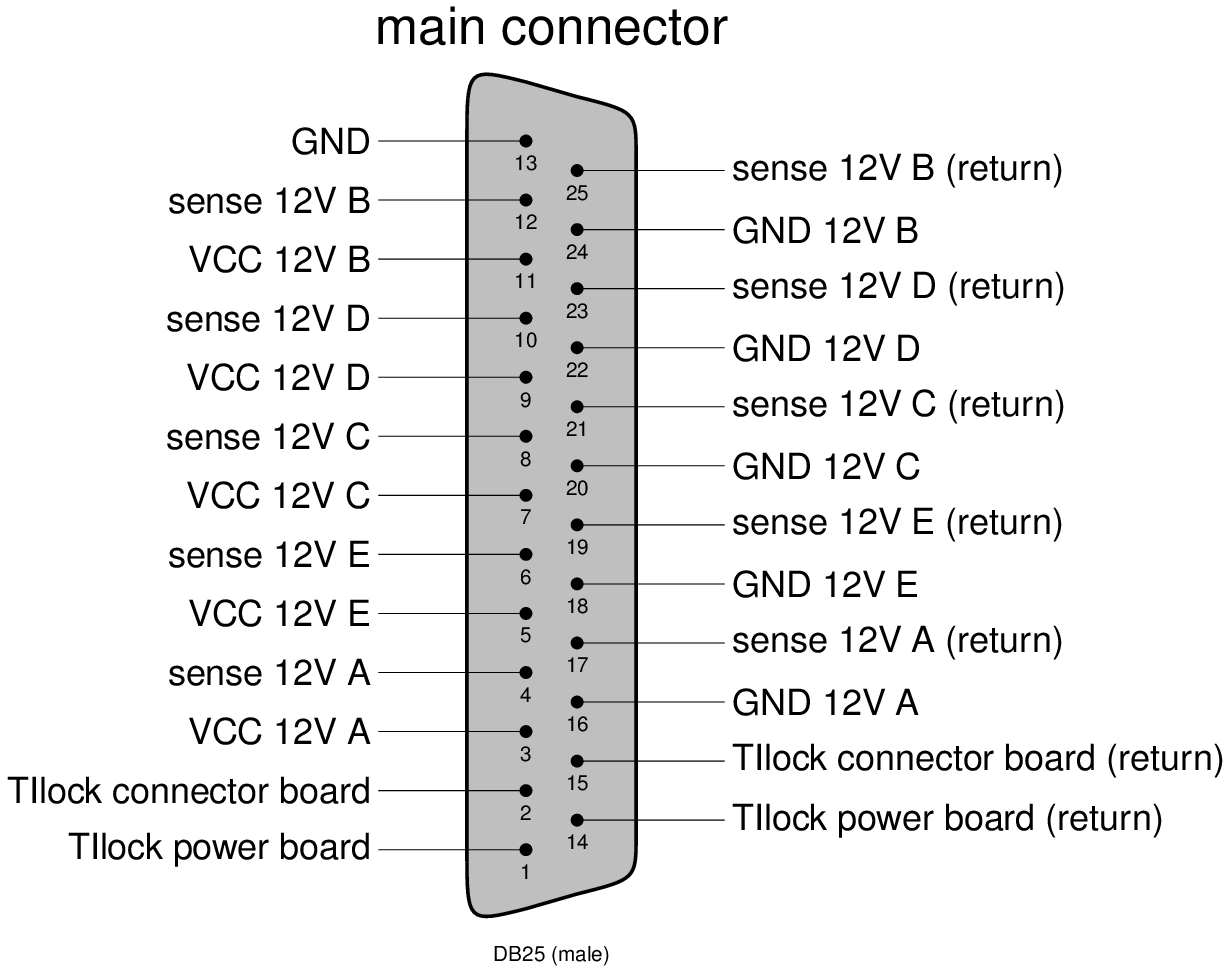
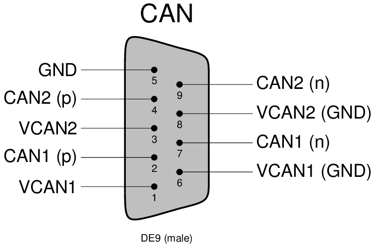
Connectors:
| 2400006,2400011 | May/2/2023 | bpol2V5 mezzanine R10 330KOhm→316KOhm to raise V1.2 to V1.24 to stablelize lpGBT3,4. Overall current 0.92->1.03A. |
| 2400006/4400069 | Nov/20/2023 | Brought in V4 board 4400069 in exchange of 2400006 to go back to Bern. |
Optobox/Board service connections:
Optobox LV/DCS services:
Check the above interfaces document for Check the above interfaces document for more detailled description.
...
Cooling and dry air inlet/outlet: FESTO 8 mm
DCS:
Currently no MOPS is mounted on the Powerboard inside the test-Optopanel (due to availability). We will ship one as soon as we got our hands on them.
SLAC Single Optoboard Test Setup
The initial single optoboard setup used for the early SLAC tests with single chip cards is summarized in the diagram below:
...
OptoBoard LV/DCS:
For optoboard standalone test setups, a mini LV/DCS service cable bundle is needed to supply 2.5V to optoboard and lead out its NTC monitoring out through the Samtec SFM-104-01-L-D connector .
Standalone optoboard power adaptor cable spec
Optoboard-FELIX Fiber Connectivity:
Each FELIX PCIe card has two MPO24 ports, serving 12 pairs of TX+RX each. Our lab test setups typically use fiber splitter bundles to breakout the MPO24 into individual LCs and use LC patch panels to map connectivity to the optoboard VTRX+ fiber pigtail. How the FELIX MPO24 port is structured is described in the FELIX readout and Direct FELIX confluence pages. There are two ways to breakout the FELIX MPO24:
- Most setups elsewhere and our easier setups all used MPO24→2xMPO12→24xLC splitters are described in the FELIX readout and Direct FELIX confluence pages.
- Our latest setups used direct MPO24→24xLC splitter in one step. The actual component inventory is in the "Fiber + patch" tab of the of test readout component Stanford Drive GoogleSheet.
How the VTRX+ fiber pigtail lines
Each fiber in the pigtail corresponds to data coming from a separate lpGBT (verification needed for RX 3 and 4):
...
Note that the Optoboard VTRX+ fiber pigtail MT ferrules connection to MPO12-LC fiber splitter is a simple slip on which requires careful manual recognition of right polarity (see ITkPixV1 readout page) which can easily slip off but prevents accidental large force breaking the fiber. It is advisable to always check the link light level with flx-info podpower to verify the fiber link is healthy (>700uW). How the VTRX+ fiber pigtail lines are structured is described in the Optosystem Interface document AT2-IP-GM-0010 (Table 4) with 5 out of 12 fibers active per optoboard . How the FELIX MPO24 port is structured and fanout with MPO24->2xMPO12→LC splitters are described in the FELIX readout and Direct FELIX confluence pages.
Current firmware allows only 2 lpGBTs to be readout, such that the link alignment string is fixed to x0000000300000000 for channels 00 and 01 in unaligned state. Alignment can be checked using data from module RX 0 (L0 on miniDP-SMA) after module configuration, giving the following link alignment strings independently of which e-links are subscribed on felixcore startup:
...
DECODING_LINK_ALIGNED_00
...
0x000000030000001
...
0x000000030000010
...
0x000000030000000
...
0x000000030001000
...
0x000000030010000
...
0x000000030100000
...
DECODING_LINK_ALIGNED_01
...
0x000000030000001
...
0x000000030000010
...
0x000000030000000
...
0x000000030001000
...
0x000000030010000
...
0x000000030100000
which can be followed from the MPO12-LC splitter fiber color coding.
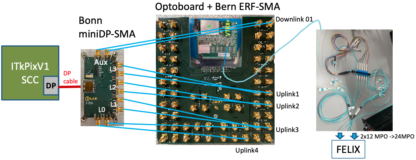
SLAC Single Optoboard Test Setup
The initial single optoboard setup used for the early SLAC tests with single chip cards is summarized in the diagram below:
| Bonn miniDP-SMA | Bern ERF-SMA | lpGBT |
|---|---|---|
| AUX | DOWNLINK 01 | 1 |
| LN3 | L1 UPLINK 01 | 1 |
| LN2 | L1 UPLINK 02 | 1 |
| LN1 | L1 UPLINK 03 | 1 |
| LN0 | L1 UPLINK 04 | 1 |
Each fiber in the pigtail corresponds to data coming from a separate lpGBT (verification needed for RX 3 and 4):
| lpGBT | VTRX+ fiber | FELIX fiber |
|---|---|---|
| 1 | red (7) | TX 1 |
| 1 | white (6) | RX 1 |
| 2 | slate (5) | RX 2 |
| 3 | brown (4) | RX 3 |
| 4 | green (3) | RX 4 |
Note that the Optoboard VTRX+ fiber pigtail MT ferrules connection to MPO12-LC fiber splitter is a simple slip on which requires careful manual recognition of right polarity (see ITkPixV1 readout page) which can easily slip off but prevents accidental large force breaking the fiber. It is advisable to always check the link light level with flx-info podpower to verify the fiber link is healthy (>700uW).
Current firmware allows only 2 lpGBTs to be readout, such that the link alignment string is fixed to x0000000300000000 for channels 00 and 01 in unaligned state. Alignment can be checked using data from module RX 0 (L0 on miniDP-SMA) after module configuration, giving the following link alignment strings independently of which e-links are subscribed on felixcore startup (for optoboard 2400006):
| miniDP-SMA Channel | Alignment String Name | Value |
|---|---|---|
| L1 UPLINK 00 | DECODING_LINK_ALIGNED_00 | 0x000000030000001 |
| L1 UPLINK 01 | DECODING_LINK_ALIGNED_00 | 0x000000030000010 |
| L1 UPLINK 02 | DECODING_LINK_ALIGNED_00 | 0x000000030000000 |
| L1 UPLINK 03 | DECODING_LINK_ALIGNED_00 | 0x000000030001000 |
| L1 UPLINK 04 | DECODING_LINK_ALIGNED_00 | 0x000000030010000 |
| L1 UPLINK 05 | DECODING_LINK_ALIGNED_00 | 0x000000030100000 |
| L2 UPLINK 06 | DECODING_LINK_ALIGNED_01 | 0x000000030000001 |
| L2 UPLINK 07 | DECODING_LINK_ALIGNED_01 | 0x000000030000010 |
| L2 UPLINK 08 | DECODING_LINK_ALIGNED_01 | 0x000000030000000 |
| L2 UPLINK 09 | DECODING_LINK_ALIGNED_01 | 0x000000030001000 |
| L2 UPLINK 10 | DECODING_LINK_ALIGNED_01 | 0x000000030010000 |
| L2 UPLINK 11 | DECODING_LINK_ALIGNED_01 | 0x000000030100000 |
There is an unstable or broken lane on the optoboard corresponding to L1 UPLINK 02, which is not present in optoboard 2400011 (currently installed). Note that alignment is sensitive to polarity of TX connection (i.e. NP↔NP vs NP↔PN) but not to the RX connections.
ITkPixV1.1 Digital Quad
The ITkPixV1.1 digital quad can be read out in two different configurations, either interfaced through the PP0+Type 0 ring (more details of the hardware setup can be found on the ITkPixV1 quad module readout page).
Interface with ring + PP0
At present the full chain including PP0 and Type 0 ring cannot be read out using FELIX. The following channel mapping is used in the connectivity file. Chips 2 and 4 send data on power-up. Chip 1 has poor data transmission quality on the negative polarity side, but is not observed using the LBL adapter card indicating that this is a feature of the ring+PP0.
| Mini-DP SMA Channel | Rx Lane | Chip ID | Chip Number |
|---|---|---|---|
| L0 | 12 | 0x15468 | 3 |
| L1 | 8 | 0x15448 | 4 |
| L2 | 4 | 0x15429 | 2 |
| L3 | 0 | 0x15428 | 1 |
Interface with LBL adapter board
Testing using the following configuration files (set in the alias mconf_quad):
connectivity: /home/itkpix/YARRdev/configs_common/connectivity/20UPGR91101015/20UPGR91101015_L2_warm.json (same as used for YARR readout)
controller: /home/itkpix/YARRdev/configs_common/controller/felix_rd53b.json
The downlink differential signal polarity should not be inverted (i.e. P↔P and N↔N SMA connections between DP and Optoboard BOB), as this is only required due to the ring channel mapping. L3,L2,L1,L0 are connected to EFF-SMA board UPLINK 00,01,02,04. Before configuration, alignment bit is unstable on UPLINK 01 (chip 2) and always 0 for other channels, but after configuration all alignment bits are zero. This is similar behavior as observed with the PP0+Ring.
| Mini-DP SMA Channel | Rx Lane | Chip ID | Chip Number |
|---|---|---|---|
| L0 | 0 | 0x15448 | 4 |
| L1 | 4 | 0x15428 | 1 |
| L2 | 8 | 0x15429 | 2 |
| L3 | 12 | 0x15468 | 3 |
Running Vivado ILA on FELIX:
The Integrated Logic Analyzer (ILA) is a feature of vivado that allows registers in ILA cores of an FPGA to be read out while in use. It is a powerful tool for debugging DAQ setups with Felix. The Felix card now has /afs/ mounted and can run release v2019.1 of vivado with a license from TID. To bring up the vivado GUI, do:
| Code Block |
|---|
ssh -Y itkpix@felix
source settings64.sh
vivado |
In the vivado GUI, select Open Hardware Manager under the Tasks list. In the green banner, select Open target > auto connect. The JTAG connection to the ILA cores of the Felix card has been fixed by Andrew and Su Dong, such that Vivado will find the ILA cores automatically. The different ILA cores can be seen in the Hardware pane under xcku155_0 (if running on Felix1 in the EPP lab). In the Trigger Setup pane, click "specify probes", click the ... button to browse files, and add the file home > itkpix > felix-fw > withILA > FLX712_PIXEL_4CH_[...]_debug_nets.ltx and select Refresh. The probes file tells vivado what signals to buffer for the ILA for that hardware. Now the waveform panel will be populated with empty ILA capture frames. To simplify viewing the bit registers in the Waveform pane, select all under Name and select Name > Short.
To capture frames, press the play button. To set up a specific ILA trigger, click the + icon in the Trigger Setup pane and pick your favorite register. The Operator and Value fields can be used to set the conditions for the trigger. Press play in the Status pane on the left; the Core status indicator shows if the ILA is waiting for a trigger or has found one, after which a limited number of frames are stored (2000 with the current setup).
The following registers can be useful to test the health of the DAQ chain:
- LinkData: 224 bits (need to check what is contained here)
- EgroupGB1Data_dbg[i]: 36-bits. Bits 33-35 are added by the gearbox: bit 35 indicates of the header is valid and bits 33-34 are the header (should be 01 if all is well). Bit 32 indicates if the data is valid.
- LinkAligned: a single bit that indicates the alignment of the optical signal between Felix and optoboard
- DecoderAligned_ila: should be 01 if uplink is aligned
- EgroupUnscrData_dbg[0]: if you see values like 87*fffff then the UPLINK polarity is inverted (it should be d78100000)
Running Remotely with FastX
FastX can be used to connect into the SLAC network for low-latency communication with nodes in the DAQ network. Information installing FastX can be found on the FastX Confluence documentation.
After installation, you can start Terminal sessions to steer the FELIX/optoboard/YARR instances. From the bastion host, run:
| Code Block |
|---|
ssh -L8081:raspi_b84_lab_felix2:8081 rddev111 |
And connect to a browser in FastX desktop to localhost:8081. From another tab, connect to http://atlascr.slac.stanford.edu:3000 and login to Grafana with
user: admin
pwd: AtlasItkAdmin
You can also open terminal windows in the FastX browser so that they stay alive when you close FastX. You will need to tunnel into itkpix@felix via <user>@rddev111.slac.stanford.edu.
GBCR Documentations
- GBCR PDR SPR and PDR (2019): Indico (Sep/12/2019), Documentation collection and report (Nov/3/2019)
- GBCR2 Specification document (register details) Nov/2019
- GBCR Testing Github
- GBCR status Jan/2023 (Jingo Ye)
The initial distribution of Optoboards to Inner System in Aug/2022 are Optoboard V2.1 with GBCR2. CMD downlink drive pre-emphasis has design issues that increased jitter to trade for some pre-emphasis. GBCR V3 design updates triplicated EQ design blocks to improve SEE immunity, and also removed passive attenuator. V3 also had another attempt to address the CMD TX design issues but dropping the DCoffset-cancellation logic due to the lack of space made the logic problematic still. The system baseline is to deploy GBCR V3 in Optoboard V4 where the GBCR CMD TX is bypassed. However, this bypass is only available in optoboard version V3 and higher.
A summary of the key GBCR control registers (based on GBCR spec document V1.2.3 from Nov/2022). There are 3 registers per GBCR input channel for independent EQ controls of each channel and another 11 registers for coming controls of retime mode and TX pre-emphasis:
| Address | Default | Bits | Name | Function |
|---|---|---|---|---|
| 0 | 0x1F | 0-2 | ch1CML_AmlSel<2:0> | Output amplitude of input RX channel 1 |
| 3-4 | ch1EQ_ATT<1:0> | EQ attenuator for input RX channel 1. | ||
| 5 | ch1dis_EQ_LF | Disable Low Frequency CTLE stage for RX input channel 1. | ||
| 6-7 | NC | |||
| 1 | 0xBB | 0-3 | ch1CTLE_MFSR<3:0> | Middle frequency (0.2-0.4 GHz) peaking strength |
| 4-7 | ch1CTLE_HFSR<3:0> | High frequency (0.4-1.6 GHz) peaking strength | ||
| 2 | 0x02 | 0 | ch1disLPF | Disable DC offset cancellation in RX input channels 1 |
| 1 | ch1disDFF | Disable DFF in input RX channel 1. RX channel works in equalizer mode. | ||
| 2 | ch1Dis | Disable RX input channel 1 | ||
| 3-7 | NC | |||
| 3-5 | Same block of registers for RX input channel 2 as address 0-2 for channel 1 | |||
| 6-8 | Same block of registers for RX input channel 3 as address 0-2 for channel 1 | |||
| 9-11 | Same block of registers for RX input channel 4 as address 0-2 for channel 1 | |||
| 12-14 | Same block of registers for RX input channel 5 as address 0-2 for channel 1 | |||
| 15-17 | Same block of registers for RX input channel 6 as address 0-2 for channel 1 | |||
| 18-20 | NC | Same block of registers for RX input channel 7 as address 0-2 for channel 1 | ||
| 21 | 0x02 | 0 | dllCapRest | Reset control voltage in DLL. |
| 1 | dllEnable | Enable DLL in phase shifter | ||
| 22 | 0x0F | 0-3 | dllChargePumpCurrent<3:0> | Set charge pump current |
| 4 | dllForceDown | Force down charge pump output | ||
| 5-7 | NC | |||
| 23 | 0x33 | 0-3 | dllClockDelayCh6<3:0> | Config clock delay of channel 6 |
| 4-7 | dllClockDelayCh7<3:0> | Config clock delay of channel 7 | ||
| 24 | 0x33 | Similar dllClockDelay control for channel 4,5 | ||
| 25 | 0x33 | Similar dllClockDelay control for channel 2,3 | ||
| 26 | 0x33 | Similar dllClockDelay control for test clk (0:3), channel 1 (4:7) | ||
| 27 | 0x70 | 0 | disTestCK | Disable Test clock output |
| 1-2 | CLK_Rx_EQ<1:0> | Config passive EQ in eRx for input clock | ||
| 3 | CLK_Rx_invData | Invert output data of eRx for input clock | ||
| 4 | CLK_Rx_enTermination | Enable the termination resistors of eRx for input clock | ||
| 5 | CLK_Rx_setCM | Set common mode voltage of eRx for input clock | ||
| 6 | CLK_Rx_En | Enable eRx for input clock | ||
| 7 | NC | |||
| 28 | 0x05 | 0-2 | Tx1_Emp<2:0> | Set pre-emphasis strength of TX channel 1 |
| 3 | Tx1_EmpDis | Disable TX channel 1 pre-emphasis | ||
| 4-7 | NC | |||
| 29 | 0x01 | 0 | Tx1dis_LPF | Disable DC offset cancellation in TX channel 1 |
| 1 | Tx1dis | Disable TX channel 1 | ||
| 2-7 | NC | |||
| 30 | 0x05 | 0-2 | Tx2_Emp<2:0> | Set pre-emphasis strength of TX channel 2 |
| 3 | Tx2_EmpDis | Disable TX channel 2 pre-emphasis | ||
| 4-7 | NC | |||
| 31 | 0x01 | 0 | Tx2dis_LPF | Disable DC offset cancellation in TX channel 2 |
| 1 | Tx2dis | Disable TX channel 2 | ||
| 2-7 | NC |
GBCR Retime mode
One major feature of the GBCR is the retime mode which is using a similar design as in lpGBT, but GBCR has a finer DLL delay granularity of 50ps per step vs 100ps in lpGBT. This is an essential utility to allow optimized control of the signal sampling time as the expected good time window at full chain loss is narrow. The control setting for this mode (recommendation and comments mostly based on exchange with GBCR designer Datao Gong):
| Register | Value | Comments |
|---|---|---|
| dllEnable | True | Enable DLL clock for for retiming |
| dllCapReset | False | |
| dllForceDown | False | DLL can have harmonic lock problem which would need dllForceDown=T to release it |
| dllChargePumpCurrent | 0x0 | Set charge injection current to min value. Higher current enables faster locking but may cause larger jitter. We care less about locking time but care more about jitter. |
| dllClockDelay | scan | Scan this delay for the active channel for good BER window bathtub. |
Vakhtang's readout software
Vakhtang Tsiskaridze (VT) wrote a standalone python package to perform digital scans outside of YARR. Use the following steps to run on felix.
For all windows (4 in total are needed):
| Code Block |
|---|
# Login and setup
ssh daq@felix # password: slacrce
cd ~/daq
source complete-setup.sh
cd ~/daq/itkdaq |
Window #1:
| Code Block |
|---|
# Monitoring for Tx sent to FELIX
./run-felix-toflx.sh |
Window #2:
| Code Block |
|---|
# Monitoring for Rx returned from FELIX
./run-felix-tohost.sh |
Window #3:
| Code Block |
|---|
# Runs an instance of felix-star
python run_readout.py |
Window #4:
| Code Block |
|---|
# Starts interactive session where configuration and digital scans are steered
python -i run_sendcmd.py>>> repower_init() # Quick power cycles the module and initializes with nominal configurations
>>> full_scan() # Must be done 2+ times, see below for example of output
>>> fec2.write_field("SLDO_VTRIM", 0xaa) # Hacky solution that fixes readout issues caused by chip 2
>>> scan() |
The output of a digital scan should appear in data, and can be plotted using the plotting script plot_occmap_quad.py.
| Code Block |
|---|
# Output after first full_scan()
[2023-12-04 16:40:44.526] [rd53b.decoder] [info] scan time: 3.77 sec, rate: 157.0 Mbps
[2023-12-04 16:40:44.526] [rd53b.decoder] [info] tval: 100, Error in pixels: 29730. vmin: 95, vmax: 24743
[2023-12-04 16:40:44.526] [rd53b.decoder] [info] tag_stats:  25600 25600 25600 25600 25600 25600 25600 25600 25543 25425 25421 25398 25378 25349 25326 25297
[2023-12-04 16:40:44.526] [rd53b.decoder] [info] tag_hits:  0 0 0 0 0 0 0 0 30099829 1 0 0 0 0 0 0
[2023-12-04 16:40:44.526] [rd53b.dataproc.quad] [info] [2] SCAN STOP
[2023-12-04 16:40:44.549] [rd53b.decoder] [info] scan time: 3.80 sec, rate: 155.6 Mbps
[2023-12-04 16:40:44.549] [rd53b.decoder] [info] tval: 100, Error in pixels: 32604. vmin: 93, vmax: 24666
[2023-12-04 16:40:44.549] [rd53b.decoder] [info] tag_stats:  25600 25600 25601 25600 25600 25600 25600 25600 25466 25336 25307 25287 25264 25236 25216 25185
[2023-12-04 16:40:44.549] [rd53b.decoder] [info] tag_hits:  0 0 0 0 0 0 0 0 30012842 0 0 0 0 0 0 9
[2023-12-04 16:40:44.549] [rd53b.dataproc.quad] [info] [1] SCAN STOP
[2023-12-04 16:40:44.572] [rd53b.decoder] [info] scan time: 3.82 sec, rate: 154.7 Mbps
[2023-12-04 16:40:44.572] [rd53b.decoder] [info] tval: 99, Error in pixels: 125302. vmin: 91, vmax: 24659
[2023-12-04 16:40:44.572] [rd53b.decoder] [info] tag_stats:  25592 25592 25592 25594 25592 25594 25592 25593 25458 25224 25314 25293 25271 25232 25208 25179
[2023-12-04 16:40:44.572] [rd53b.decoder] [info] tag_hits:  0 0 0 1 2 1056 0 6 29930769 0 0 0 0 0 0 0
[2023-12-04 16:40:44.572] [rd53b.dataproc.quad] [info] [0] SCAN STOP
[2023-12-04 16:40:44.594] [rd53b.decoder] [info] scan time: 3.84 sec, rate: 153.9 Mbps
[2023-12-04 16:40:44.594] [rd53b.decoder] [info] tval: 100, Error in pixels: 31999. vmin: 93, vmax: 24668
[2023-12-04 16:40:44.594] [rd53b.decoder] [info] tag_stats:  25600 25600 25600 25600 25600 25600 25600 25600 25468 25341 25306 25289 25264 25230 25215 25184
[2023-12-04 16:40:44.594] [rd53b.decoder] [info] tag_hits:  0 0 0 0 0 0 0 0 30016538 0 0 0 0 0 0 0

# Output after setting VLDO_TRIM on fec2
[2023-12-04 16:53:59.413] [rd53b.decoder] [info] scan time: 3.74 sec, rate: 92.1 Mbps
[2023-12-04 16:53:59.413] [rd53b.decoder] [info] tval: 100, All pixels are good.
[2023-12-04 16:53:59.413] [rd53b.decoder] [info] tag_stats:  25600 25600 25600 25600 25600 25600 25600 25600 25600 25600 25600 25600 25600 25600 25600 25600
[2023-12-04 16:53:59.413] [rd53b.decoder] [info] tag_hits:  0 0 0 0 0 0 0 0 15360000 0 0 0 0 0 0 0
[2023-12-04 16:53:59.413] [rd53b.dataproc.quad] [info] [1] SCAN STOP
[2023-12-04 16:53:59.436] [rd53b.decoder] [info] scan time: 3.76 sec, rate: 91.6 Mbps
[2023-12-04 16:53:59.436] [rd53b.decoder] [info] tval: 100, All pixels are good.
[2023-12-04 16:53:59.436] [rd53b.decoder] [info] tag_stats:  25600 25600 25600 25600 25600 25600 25600 25600 25600 25600 25600 25600 25600 25600 25600 25600
[2023-12-04 16:53:59.436] [rd53b.decoder] [info] tag_hits:  0 0 0 0 0 0 0 0 15360000 0 0 0 0 0 0 0
[2023-12-04 16:53:59.436] [rd53b.dataproc.quad] [info] [2] SCAN STOP
[2023-12-04 16:53:59.458] [rd53b.decoder] [info] scan time: 3.78 sec, rate: 91.0 Mbps
[2023-12-04 16:53:59.458] [rd53b.decoder] [info] tval: 100, All pixels are good.
[2023-12-04 16:53:59.458] [rd53b.decoder] [info] tag_stats:  25600 25600 25600 25600 25600 25600 25600 25600 25600 25600 25600 25600 25600 25600 25600 25600
[2023-12-04 16:53:59.458] [rd53b.decoder] [info] tag_hits:  0 0 0 0 0 0 0 0 15360000 0 0 0 0 0 0 0
[2023-12-04 16:53:59.458] [rd53b.dataproc.quad] [info] [0] SCAN STOP
[2023-12-04 16:53:59.481] [rd53b.decoder] [info] scan time: 3.80 sec, rate: 90.5 Mbps
[2023-12-04 16:53:59.481] [rd53b.decoder] [info] tval: 100, All pixels are good.
[2023-12-04 16:53:59.481] [rd53b.decoder] [info] tag_stats:  25600 25600 25600 25600 25600 25600 25600 25600 25600 25600 25600 25600 25600 25600 25600 25600
[2023-12-04 16:53:59.481] [rd53b.decoder] [info] tag_hits:  0 0 0 0 0 0 0 0 15360000 0 0 0 0 0 0 0
|
Additional notes:
- 17 different triggers, on 9th trigger getting all hits
- Scan time (~4 seconds), rate is per chip
- Number of tag hits should be 400 * 384 * N_triggers
- If you run 100 triggers, scan time is dominated by mask stepping
...
Some Useful Links
- Optoboard System Documentation
- FELIX JIRA (Oct/22) on optoboard + ITkPix readout setup
- CERN mattermost Bern-Optoboard channel
- Talk (Dec/9/2022) by Angira Rastogi on Optoboard-FELIX setup at LBNL
...