...
- Connect KCU105 board to PC via JTAG (make sure the cable supports sending data)
- Launch Vivado Lab
- In slacrce terminal, type:
- source /afs/slac.stanford.edu/g/reseng/xilinx/vivado_2022.2/Vivado/2022.2/settings64.sh
- vivado &
- In slacrce terminal, type:
- Green Banner: Open New Target → Set JTAG Clock Frequency 30,000,000 (why?)
- Green Banner: Program device → Select 1p5625_example_ibert_ultrascale_gth_0.bit
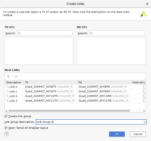
- Green Banner: Create Links → Add all 4 links using the "+" sign
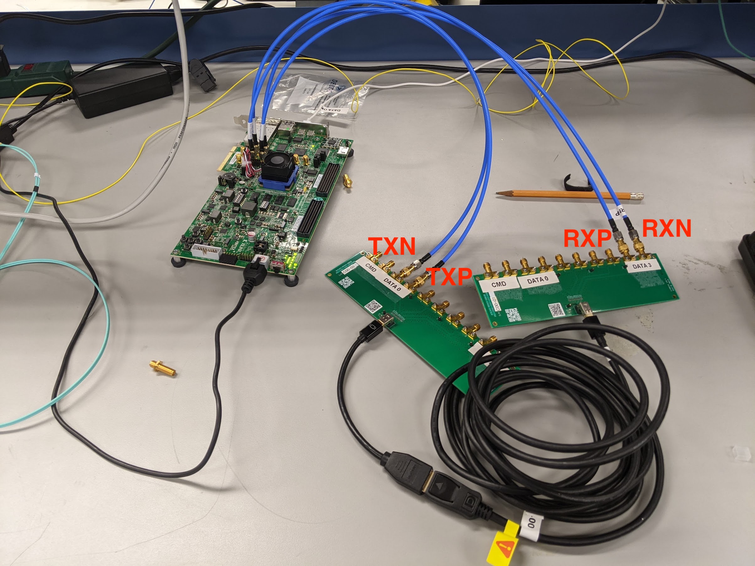
- Connect cables. There are 2 for transmission positive / negative (TXP/TXN) and 2 for receiving positive / negative (RXP/RXN) which are labeled on the KCU board. Since a single DP reverses the data lane connections, the connections on the two SMA to mDP adapter board should be matched as CMD → CMD, data0 → data3, data1 → data2, etc.
- To validate the setup we will do a simple eye scan with the KCU board. This requires us to also have the the P/N cables connected in the right order (remember to account for the flip in the data lanes). See below picture for the correct setup for data lanes. If you are only using the board to drive a signal to the oscilloscope the P/N polarity doesn't matter
- If everything is connected properly one of the links should be up which shows that the KCU board can receive the signal it is sending
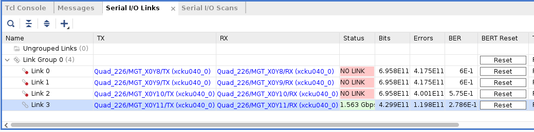
- Select the link which is up (Link 3 here) → Create Scan. Here you can specify the BER as well as the horizontal/vertical increments
- If you see an eye then the setup works. Unfortunately the setup does not give the amplitude of the RX signal (requires recompiling the firmware?) so we will do all quantitative measurements with the oscilloscope. Connect the RX side to the oscilloscope now and follow the further instructions below.
...