Outline
- Ring Loading Tooling, 19-1 RD53a
- Handling Frame, 19-1 RD53a OB Stave
- Shipping Box, 19-1 RD53a OB Stave
- Stave Loading Tooling, 19-1 RD53a OB Stave
Ring Loading Tooling
Ring loading glue locations drawing (not released): REF-000160474 (LOADING FIXTURE, 19-1 RING).pdf
Ring Loading Tooling Drawings: 19-1 Ring.zip
- In the future, review drawings in Mechanics meeting and release/add to Windchill CAD library, to reduce risk of interface issues.
Ring loading glue locations drawing (not released): REF-000160474 (LOADING FIXTURE, 19-1 RING).pdf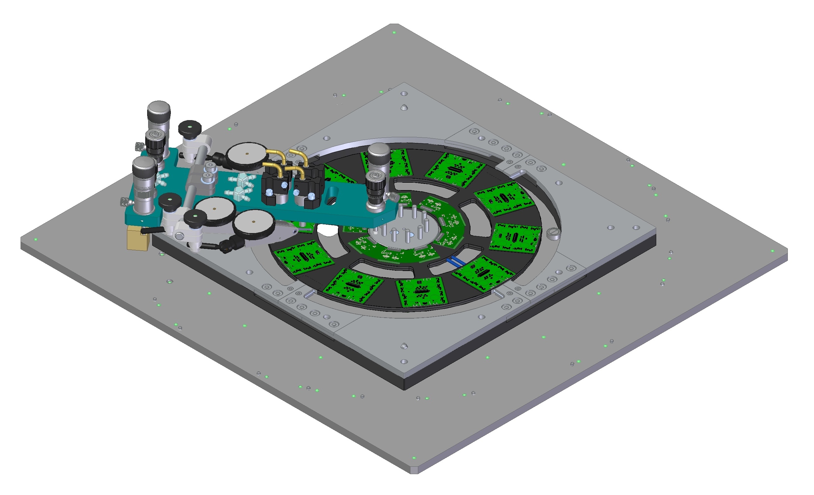

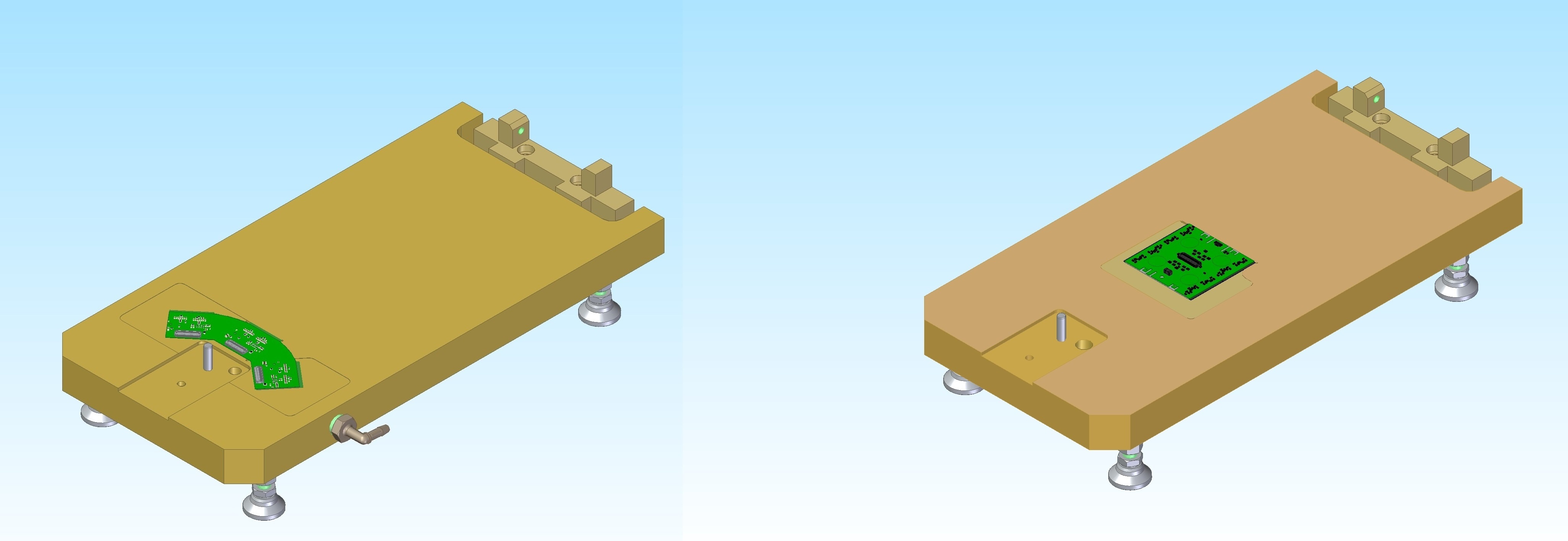
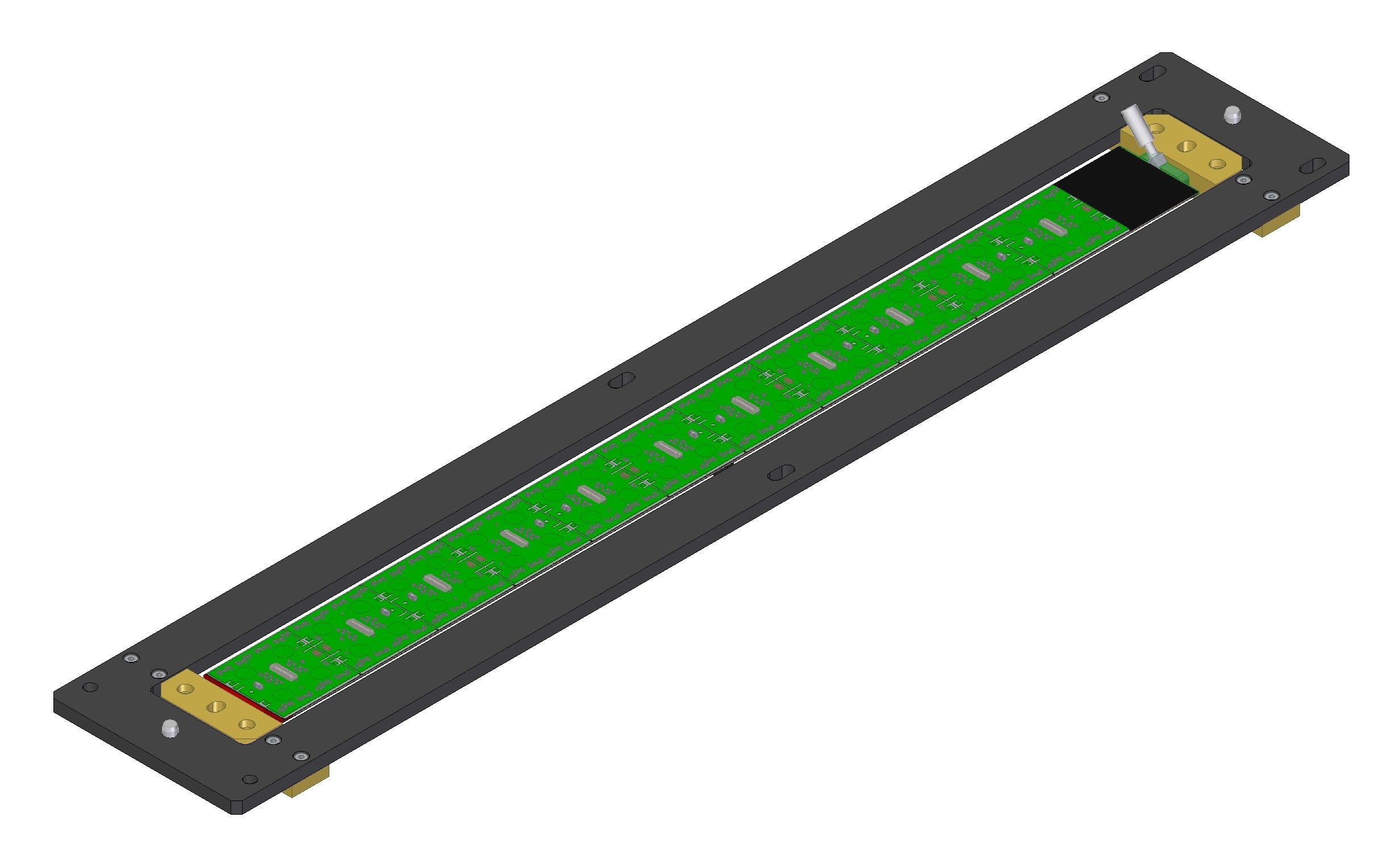
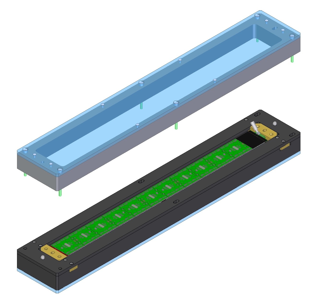
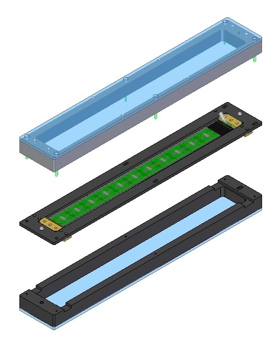
Handling Frame and Shipping Box
Handling Frame and Shipping Box added for Stave. Drawings created (not yet reviewed/ released) for shipping box.
Shipping box drawings draft Drawings (not released):
Handling Frame:
Interface block to join Stave and Handling Frame (not released):


Shipping Box:

Stave Loading Tooling
...
- Total for all:
- Limit: +/-.075mm
- Root sum square: +/-.026mm
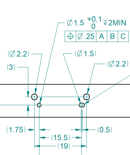
Notes for design of 19-1 Stave tooling:
- Re-use tooling where possible.
- Using beads to set glue thickness; no longer need dial indicators or differential adjusters.
- Use 2 sets of micrometer adjusters (absolute scale).
- Consider adding soft material to vacuum pads.
- Reconfirm that Stave and Module CADs / drawings are compatible with tooling, before manufacture.
- Use dowel pins and screw interface to ends of Stave (locate same as in production assembly).
- Consider longer dowel pins in the baseplate (help locate the bridge, without pivoting).
- Consider handling frame integration.
Some past presentations:
- 30 March 2021: Tooling and Plans for Loading, 19-0/1, Stave and Ring