Content
2018-12-04
On 2018-12-04 we was working with Gabriel to fix fit issue from potentially lost events/frames.
Code was committed to https://github.com/lcls-psana/Detector/blob/master/src/UtilsEpix10kaCalib.py
on the top of the release ana-1.3.82.
However, test of the offset etc. evaluation procedure like
bsub -o log04 -q psanaq epix10ka_offset_calibration -e xcsx35617 -d XcsEndstation.0:Epix10ka2M.0 -r544 --idx=4 --nspace=5 -p
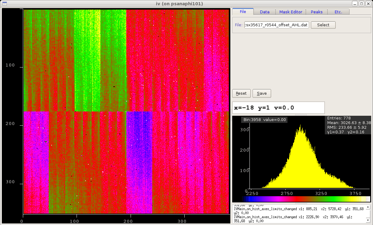
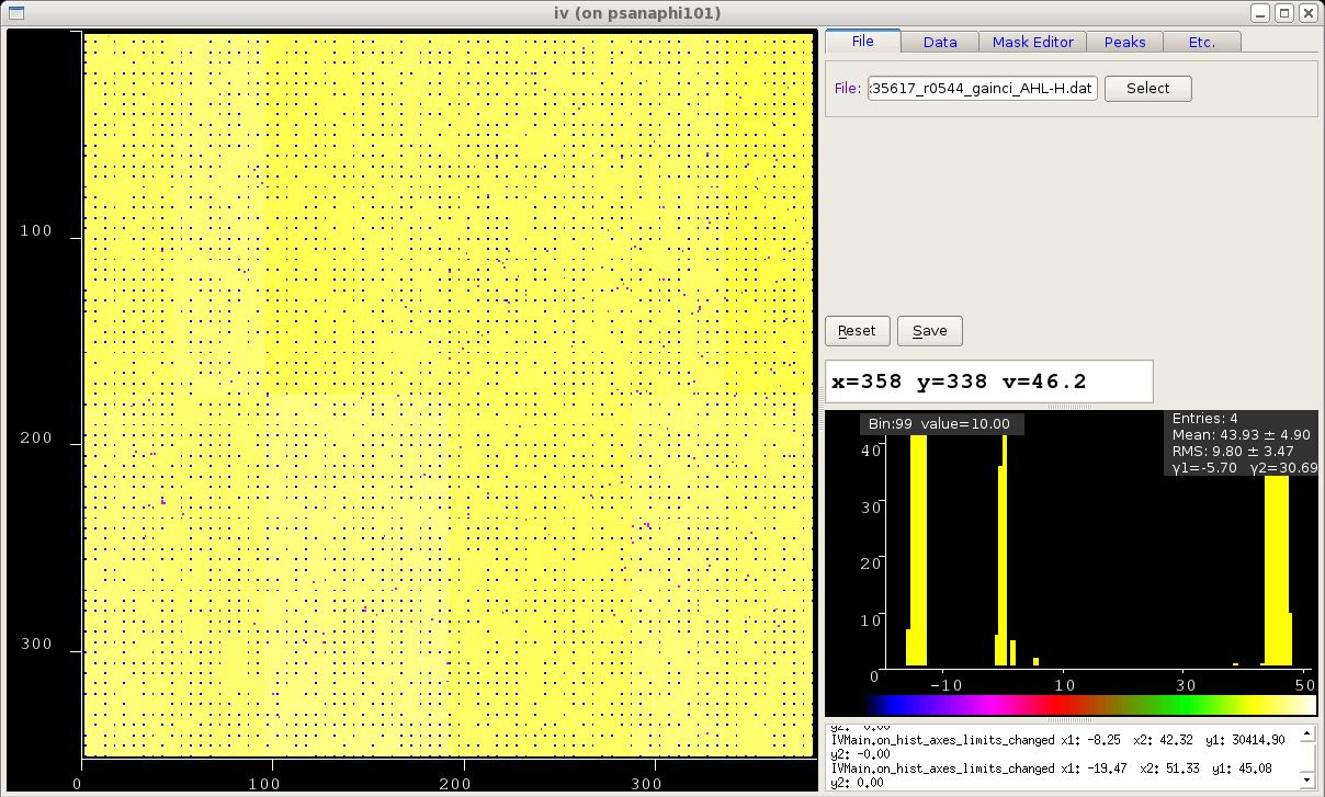
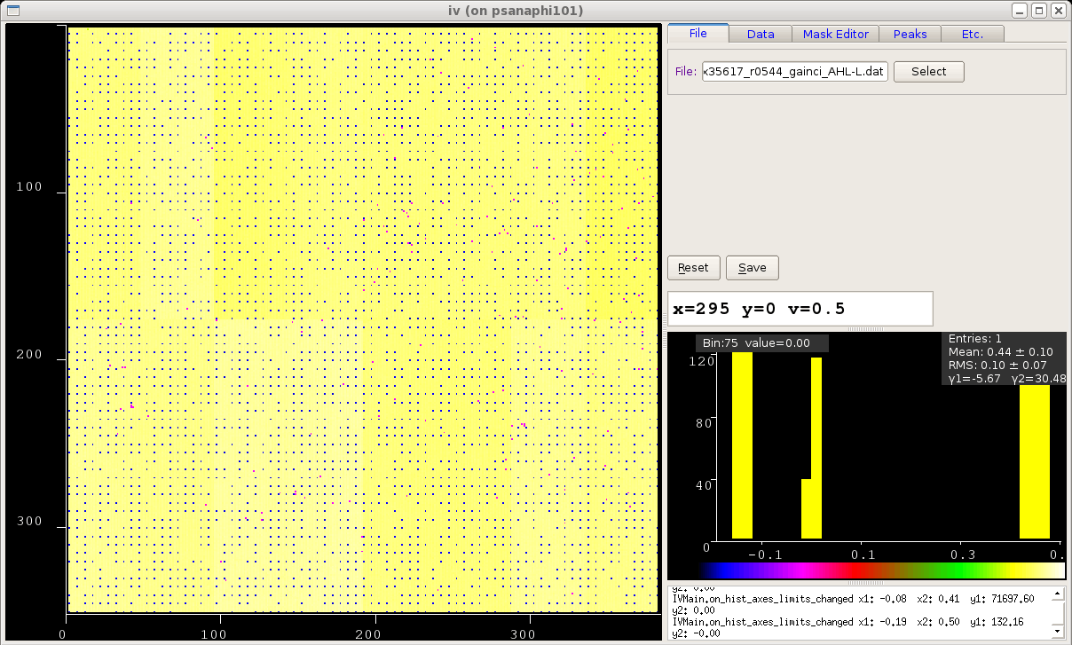
shows that offsets, gains, and evaluated pedestals have some problem:
img-epix10ka_0006_20181129124822_xcsx35617_r0544_offset_AHL.png Previous version of the fit did not show this issue img-epix10ka_0007_20181129124822_xcsx35617_r0544_offset_AHL-old.png

img-epix10ka_0006_20181129124822_xcsx35617_r0544_gainci_AHL-H.png
img-epix10ka_0006_20181129124822_xcsx35617_r0544_gainci_AHL-L.png
Although AML shows normal results:
img-epix10ka_0006_20181129124822_xcsx35617_r0544_gainci_AML-M.png

img-epix10ka_0006_20181129124822_xcsx35617_r0544_gainci_AML-L.png

2020-06-10
Directories
/reg/d/psdm/det/detdaq18/xtc
/reg/d/psdm/det/detdaq18/calib/Epix10ka2M::CalibV1/DetLab.0:Epix10ka2M.0/pedestals/
/reg/g/psdm/detector/gains/epix10k/panels/
exp=detdaq18:run=20 - 103 calibcycles, last dark calibcycle does not have configuration for AHL-L and can't be used. All 2x7x7charge injectionb cc should be good.
event_keys -d exp=detdaq18:run=20 -m3
DetLab.0:Epix10ka2M.0
Issue
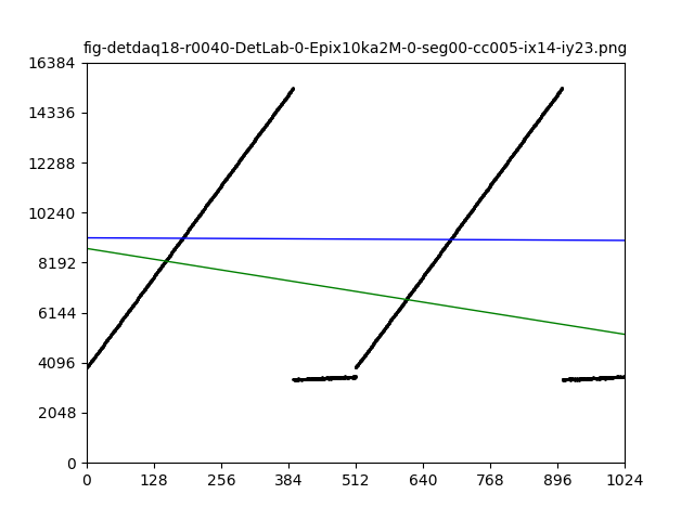
epix10ka_offset_calibration -e detdaq18 -d DetLab.0:Epix10ka2M.0 -r40 --idx=0 -P --nspace=7 -o ./work
fit does not work for all injection points...


2020-06-18 Calibration procedure for pedestals using charge injection
Reconstruction of data in analysis
<calibrated-data> = (<raw-data> - pedestal) * <gain-factor>
where pedestals and <gain-factor> are per-pixel map combined from 7 gain mode maps.
Calibration procedure
Accumulate dark data and evaluate pedestal for five gain modes:
- 5 calib-cycles: FH, FM, FL, AHL-H, AML-M (gain is not switching in dark)
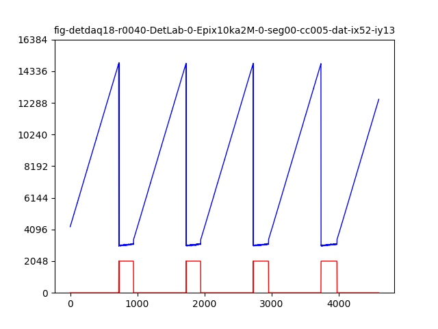
and 2x49 charge injection samples (see plots) where gain is switching: - 7X7 calib-cycles: AHL
- 7X7 calib-cycles: AML
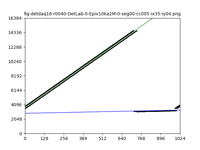
In charge injection samples each pixel has data and fit results as shown on plots.
Assuming that each gain mode intensity sample is parametrized as
<intensity> = B + <charge-index> * G
each pixel has constants like
- offset_AHL-L, offset_AHL-H, and evaluate their difference offset_ahl = H-L
- offset_AML-L, offset_AML-M, and evaluate their difference offset_aml = M-L
Then, in current calibration procedure we evaluate pedestal for two leftover gain modes AHL-L, AML-L as
- pedestal_AHL-L = pedestal_AHL-H - offset_ahl
- pedestal_AML-L = pedestal_AML-H - offset_aml


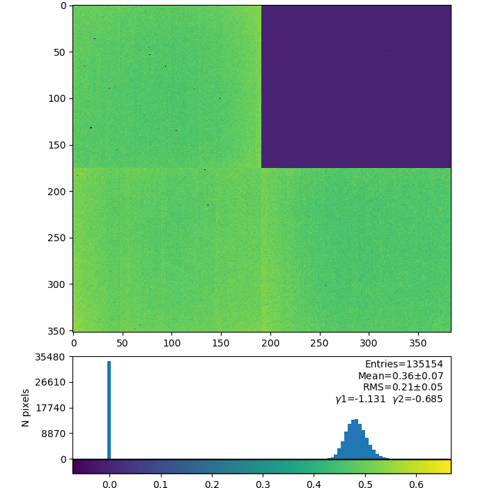
Panel results
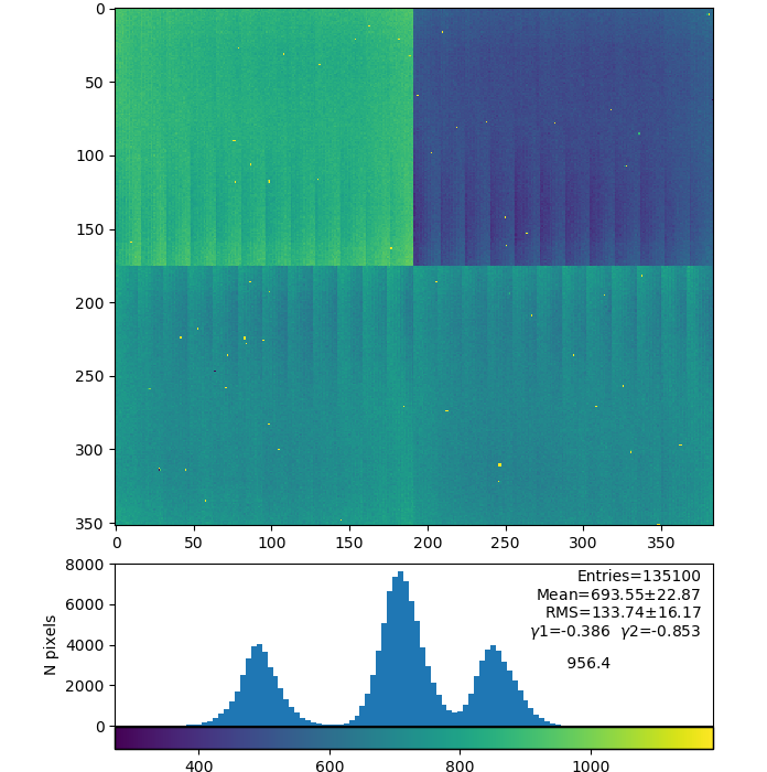
detdaq18 run 52
Panel 2(counting from 0) /reg/g/psdm/detector/gains/epix10k/panels/0000000001-0175233793-0553648150-0743498629-0017156647-0000000000-0000000000
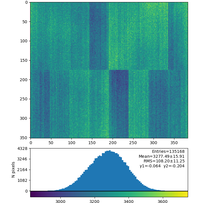
Pedestal for fixed gain modes FH, FM, FL


Pedestal for switching gain modes AHL-H and derived AHL-L AML-M and derived AML-L


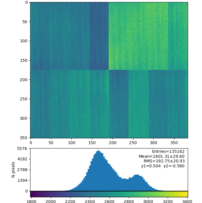
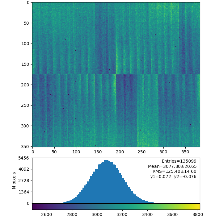
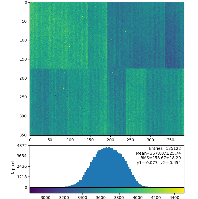
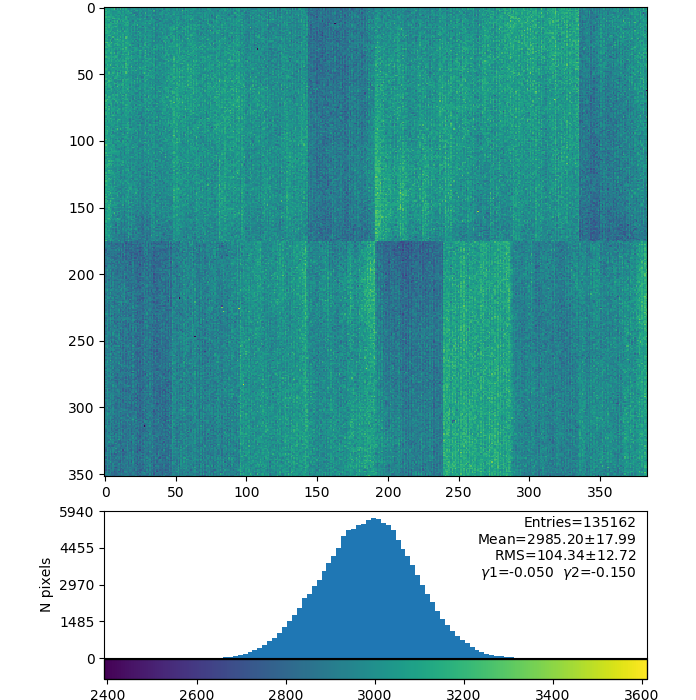
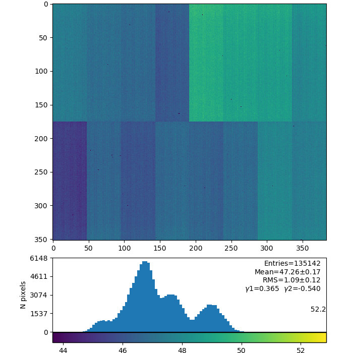
Offset (B) for switching gain modes AHL-H, AHL-L, AML-M, AML-L

Offsets difference H(or M) - L for AHL, AML

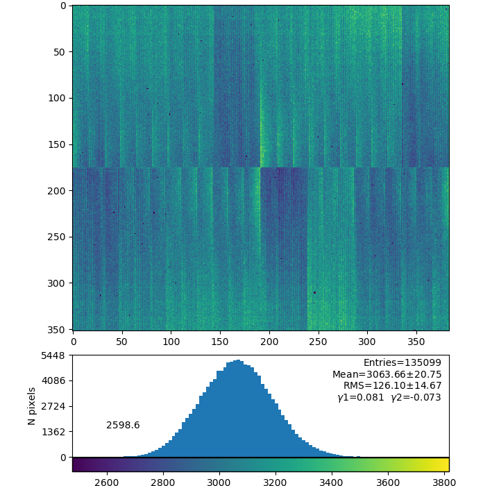
Gains (G) for switching gain modes AHL-H, AHL-L, AML-M, AML-L


Mean values
| Fixed gain mode | FH | FM | FL |
|---|---|---|---|
| pedestal | 3392 | 3293 | 3277 |
| Switching gain mode | AHL-H | AHL-L | AML-M | AML-L |
|---|---|---|---|---|
| pedestal H(M)-from dark, L-evaluated | 3332 | 1825 | 3295 | 2601 |
| offset (B) from fit | 4584 | 3077 | 3679 | 2985 |
| offset (B) difference H(M)-L | 1507 | 694 | ||
| gain (G) from fit | 47 | 0.52 | 15.4 | 0.49 |
Denote
- p - pedestal
- B - fit base-level offset parameter, <intensityADU> = B + G * <event-index-from-0-pulser>
- G - gain
Current (plots above and results in table) naive version of L-pedestals evaluation
- pL = pH - (BH-BL)
Gabriel's version
- pL = BL - (BH-pH)*GL/GH

L-pedestals using Gabriel's formulae for AHL-L and AML-L

Questions
- do we need to account for the difference between offset (B) and pedestal (Gabriel's version)
- the same difference may be between fit B(L) and pedestal(L) OR it is smaller due to the gain?
- is current procedure correct?
- if not
- what is correct procedure?
- or what could we calibrate with charge injection?
2020-06-22 ASIC issue
detdaq18 run 52
Panel 14 (counting from 0) /reg/g/psdm/detector/gains/epix10k/panels/0000000001-0175696641-1056964630-1010951301-0019435010-0000000000-0000000000
Data for a few charge injection points
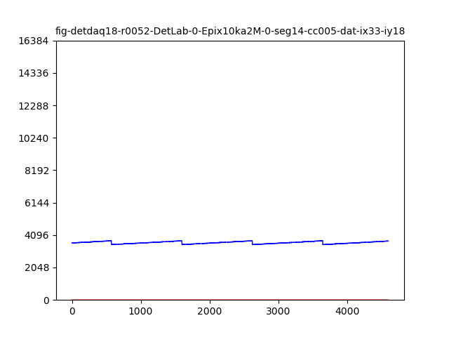


Injected charge or gain is too small to switch to L-gain mode...
Gains AHL-H, AHL-L, AML-M, AML-L


Panel 14(next-to-last) charge injection in ASIC1 does not work
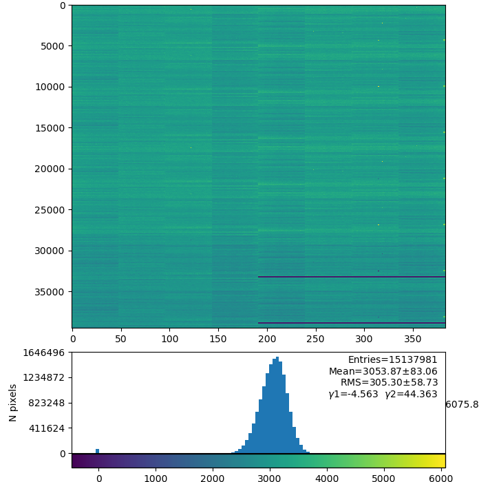
2020-06-24 calibration constants for ALL gain ranges and panels
detdaq18 run 52
pL were evaluated using Gabriel's formulae.
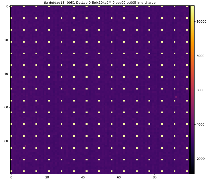
plots for pedestals, pixel_rms, pixel_status, pixel_gain (default), gain from charge injection
![]()
![]()
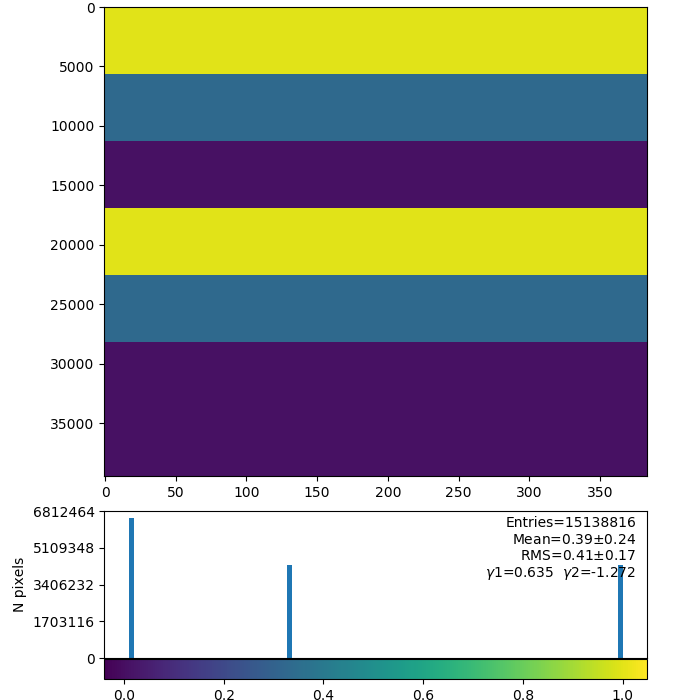

deployed as
/reg/d/psdm/det/detdaq18/calib/Epix10ka2M::CalibV1/DetLab.0:Epix10ka2M.0/*/52-end.data
SHAPE (7,16,352,384) : 7-gains, 16-panels of shape (352,384)
References
Overview
Content Tools