Identification
Firmware | xxxx | updated date | |
|---|---|---|---|
| Module identifiers | |||
Verify Nominal Operating Voltages and Currents
Environmental
Test conditions:
- Detector running and stabilized for two hours, nominal settings.
- Beam monitor shows ~0.75mJ.
Record thermometer and humidity sensor readings:
Sensor Airbox T 39.64C Airbox Humidity 0.96% Airbox Pressure 1007 hPa Dewpoint -25.4C Coldplate C 23.34C Coldplate D 24.01C Chiller Flow 2.3 l/m Chiller Setpoint 15C Note that airbox temp rose to 40.3C after awhile. Experimented with chiller temp and verified that dropping 5C started slowly cooling the airbox. Got down below 39c, but decided to return to 15C on the chiller for comparability with lab data. May want to change standard operating temperature in future, but table that for now.
- Wave8 beam monitor in sample chamber appears to be blocked by the liquid jet shroud so we're unable to provide witness flux monitoring tonight....shroud will come out tomorrow so we can try again.
Electrical
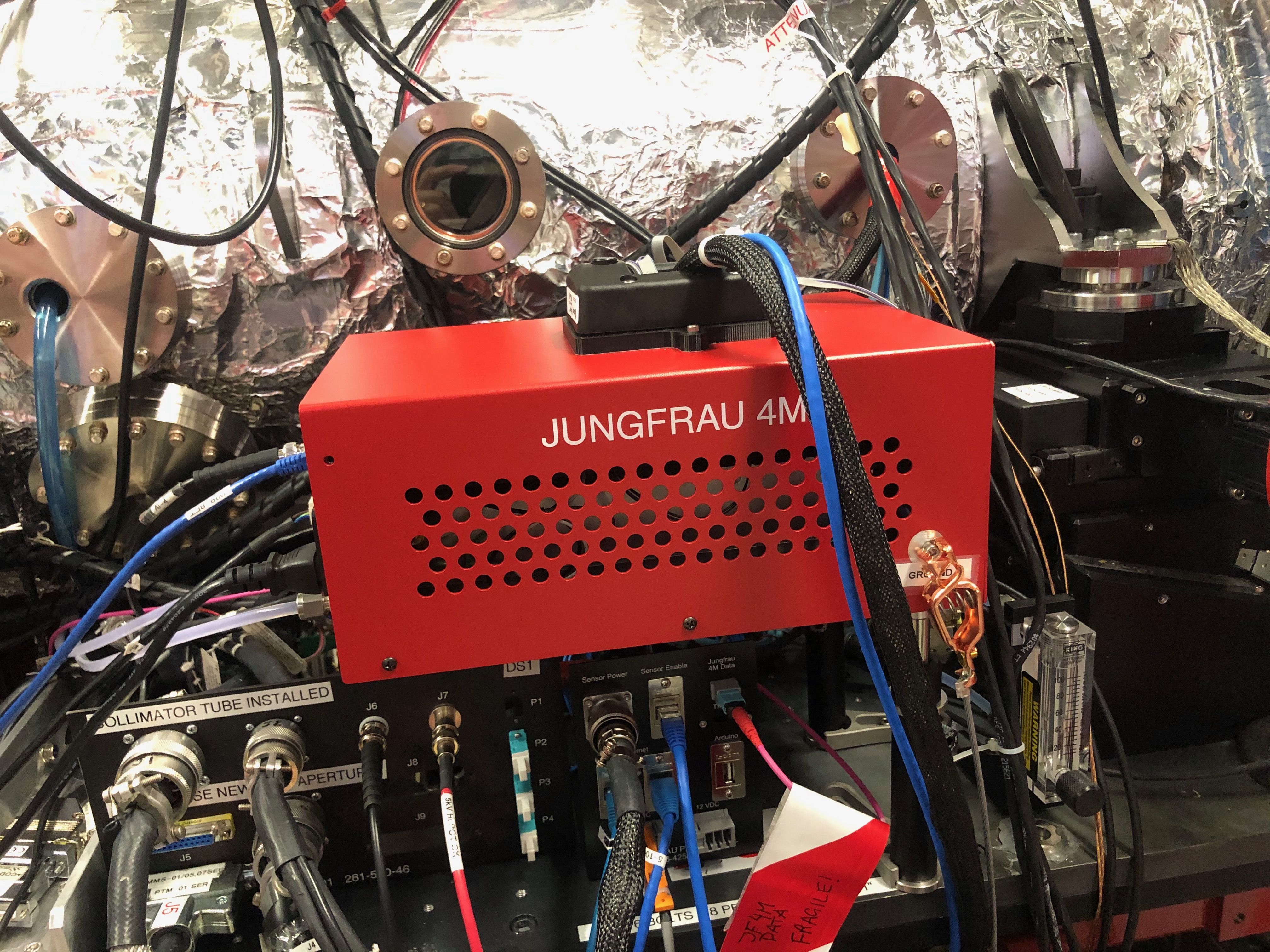
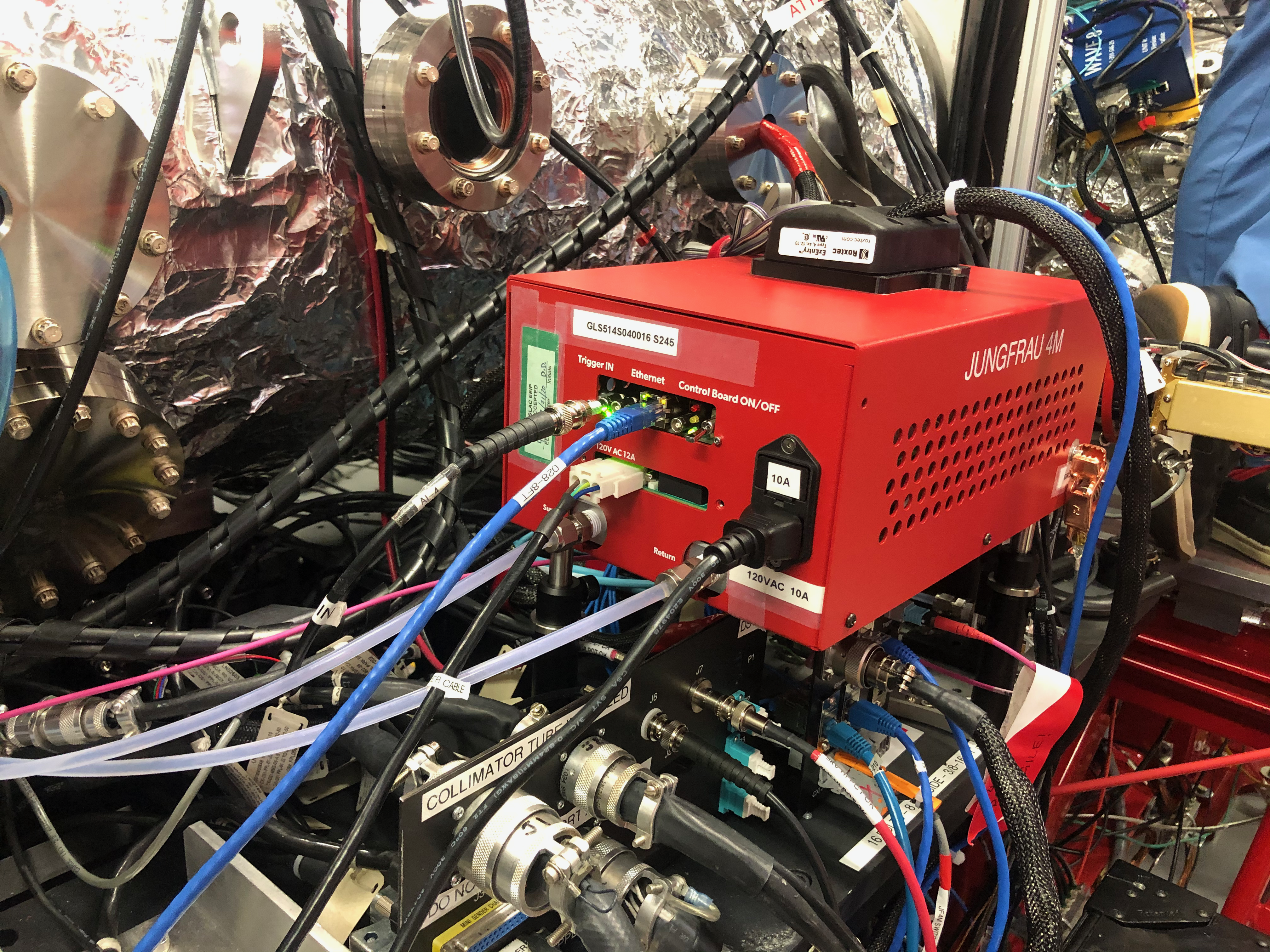
- Document grounding scheme: Heavy clip ground wire to power supply chassis, nothing else visible:
- Read/record all available voltages and currents
Power Supply | |
|---|---|
| Temp | 29.3C |
| Voltage | 11.792V |
| Current | 25.509A |
Performance
- Darks in Autogain mode as Run 111
- Set Forced Gain 1
- Darks in ForcedGain1 as Run 112
- Set ForcedGain2
- Darks in ForcedGain2 as Run 113
- Create pedestals with 'makepeds -J'
- Collect flat field off Cu foil as Run 115 (3e-4 attenuation)
- Move detector back 400mm, same attenuation, hopefully flatter field as Run 116.
- Move detector up close, set attenuation @1e-3, flat field as Run117.
- Jacking up to 100% beam we are burning through the Cu but not getting any switching.
- Try scanning foil to catch a bright shot before it burns through (Run 118)
- Switch to metallic glass target @100%, scan to burn new holes in Run 119.
- 1e-3 attenuator on metallic glass for flat field in Run 120.
- Start water jet. 100% beam and water ring in 121 and 122.
- Lysozyme jet in Run 123 & 124:
- Place detector behind gate valve, vent, remove liquid jet shroud.
- Insert Ag behgenate, check out Wave 8 timing (no longer behind the shroud).
- Kaz is able to verify Wave8 is timed in properly.
- END DAY ONE.
Day two was mostly washed out by inability to run the detector due to DAQ config error. Did verify timing delay or 231us.
Day 3: Looking to generate enough flux per shot to trigger autorange in the JF. Problem is that fluorescence foils burn through immediately and we see greatly reduced flux. A script has been written to reposition the foil once per shot so that we're continuously using new foil.
- Sample ladder has metallic glass, 25um Cu foils, and doubled Cu foil loaded.
Plan to go:
- Force high gain mode
- Collect 1000 darks for analysis (Conny test 1; pedestals, noise, bad pixel map)
- Force medium gain
- Collect 1k darks (C2, pedestals/offsets, noise, bad pixel map)
- Force low gain
- Collect 1k darks (C3, pedestals/offsets, noise, bad pixel map)
- Offsets due to ambient visible light
- Viewports open/closed
- In-chamber lights
- Any laser sources planned
- Mechanical
- Verify range of motion (done by CXI)
- Verify non-interference gate valve operation (done by CXI)
- Record encoder readings for position scaling
- Assess
- If operation is nominal, move on to next block
- If time allows, vary airflow +/- 20% to check dependence
- Return gain to autoranging
1) Beam set up (12h, full shift) (wave8 monitoring throughout) (t = 0)
- No sample (60 min)
- Set max attenuation
- Pass beam through beam pipe to check alignment, systematics and baseline scatter.
- Collect 1k frames for analysis. Expect ~no signal.
- Set midrange attenuation
- Collect 1k frames for analysis.
- Set zero attenuation
- Collect 1k frames for analysis.
- Assess
- If operation is nominal, move on to next block
- If time allows consider other attenuations, moving in z
- Return to max attenuation
- Sample setting (TBD) (t = 1h)
- Set z mid-range
- Attenuator scan (1.5h)
- Assess flux level. If satisfied, continue at z-scan step. Otherwise:
- Adjust sample jet (setting B)
- Attenuator scan (1.5h)
- Assess flux level. If satisfied, continue at z-scan step. Otherwise:
- Adjust sample jet (setting C)
- Attenuator scan (1.5h)
- Assuming that we’ve got a good flux level, move to z-scan
- Set attenuator for moderate-flux level and scan in z (60 min) (t = 5.5h)
- Move detector close to sample point
- Collect 1k frames for analysis
- Move detector far from sample point
- Collect 1k frames for analysis
- At this point we believe the beam/sample are well adjusted and understood, move on to commissioning signal tests.
- Re-set to mid-range in z.
- If time allows, move on to next block early.
- High gain flats (fixed gain) (t = 6.5h)
- Set sample and choose attenuator range (30 min)
- Run attenuator scan (60min)
- Set attenuator mid-range
- Vary integration time (if this is possible) (60)
- If time allows:
i. Vary bias +/- 20%
- Medium gain flats (fixed gain) (t = 9h)
- Set sample and choose attenuator range (30 min)
- Run attenuator scan (60min)
- Set attenuator mid-range
- Vary integration time (if this is possible) (60)
- If time allows:
i. Vary bias +/- 20%
- Low gain flats (fixed gain) (t = 11.5h)
- Set sample and choose attenuator range (30 min)
- Run attenuator scan (60min)
- Set attenuator mid-range
- Vary integration time (if this is possible) (60)
- If time allows:
i. Vary bias +/- 20%
- Full range flats (autoranging) (t = 14h)
- Set sample and choose attenuator range at widest possible (30 min)
- Run attenuator scan (60min)
- Set attenuator mid-range
- Vary integration time (if this is possible) (60)
- If time allows:
i. Vary bias +/- 20%
- Repeat baseline tests (3h) (t = 17h)
- End (t = 20h)
Performance Measures
Pedestal
Method: Dark environment, nominal operation, collect 1000 frames @120Hz. Generate per-pixel mean and standard deviation over 1000 frames. Pixels more than 3 sigma out of detector-wide mean are flagged bad. Files archived as xxxxx.
Summary Values
| Date | Mean | StdDev | #Bad |
|---|---|---|---|
Pedestal Map
Noise map
Gain and uniformity (photon source)L
Linearity (signal injection)
Thermal measurements (all thermometers)
Experiment History
| Experiment | Hutch | Shifts | Date Deployed |
|---|---|---|---|
| Commissioning | MFX | 1 | 15 June 2020 |
Calibration Records
| Date | Hutch | Date | Record link | Comment |
|---|---|---|---|---|
| Commissioning | MFX | 7/29/20 | 15 June 2020 |