IP address: 134.79.218.154

Subnet Mask: 255.255.252.0

Default Gateway: 134.79.219.1


IP address change:

  1. Control panel
  2. View network status and tasks
  3. Click on ethernet connection
  4. Properties
  5. Internet Protocol Version 4(TCP/IPv4) → properties
  6. Change IP address to 134.79.218.--- (like 100)
  7. Subnet mask to 255.255.252.0
  8. No need for default gateway


What to do?

  • Retrieve parameters
  • save them on a file on the pc
  • Address the questions of the SmartMotor on the controller
  • Figure out how to connect the motors to the controller


Aerotech BMS60-A-D25-FLB-E1000ASH-15DM (BRUSHLESS MOTOR):

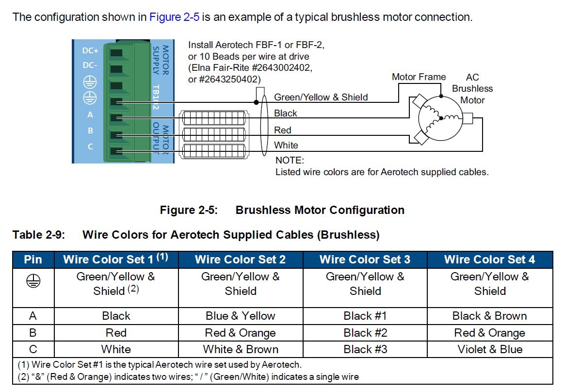
fig 1: brushless motor connections

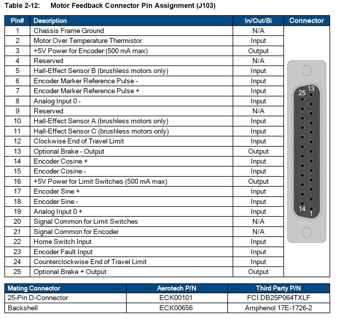
fig 2: feedback connections
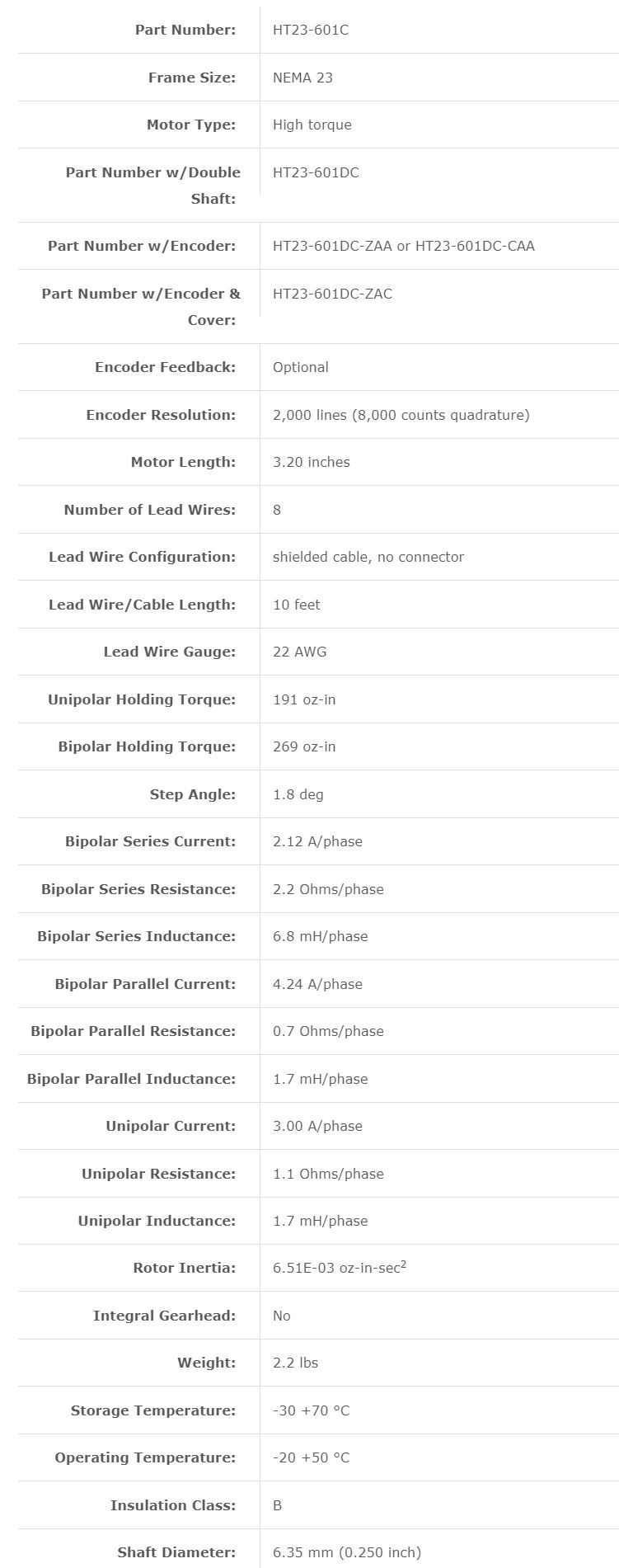

fig 3: specs

Initiating Ensemble:

  • Connect to LAN cable
  • Connect motors as shown in pic on the left
  • Controller→ connect to connect
  • Enable or write ENABLE @0 in the Execute Command

Notes:

  • PositionFeedback I assume is feedback from encoders (cnts)
  • ProgramPositionFeedback is feedback in (deg)
  • current command and current feedback to monitor current
  • How is the direction of motion defined and units
    • positive is CW


Command motions to keep track of:

  • LINEAR X 20 F 100 (works without F)
    • Goes distance 20 at speed 100 on axis X. Linear motion
  • prog_dist= CMDPOS (X)
    • Gets the command position (enc counts)
  • temp_dist= EXTPOS (X)
    • Gets external position of axis
  • temp_val= GETPARM(X, GainKpos)
    • retrieves a single parameter for specific axis or task
  • HOME X Y
    • Return to their reference positions (home)
  • temp_current = ICMD (X)
    • return current command in amps
  • FREERUN X 200 Y 300
    • Keep running without a specified distance, just speed
  • OSCILLATE X, 5000.0, 1.0, 2, 3
    • OSCILLATE <Axis>, <Distance>, <Frequency>, <Cycles> , <NumFreqs> (last not necessary)
    • Generate sinusoidal oscillations on an axis
  • temp_dist= PCMD(X)
    • Return the position commanded to the servo in (user units)
  • MOVEABS X 5 XF 10


How I fixed the task error: not activated feature:

  •  FeatureNotEnabled
  • Set them to default values, or 0
  • Or basically: Axis → Enhanced Tracking Control → EnhancedTrackingSetup was set to 1 changed to 0

Parameters:

  • FaultMask Parameter:
    • Use it to define the axis fault conditions detected by the controller 
    • You can configure what the axis does for each fault  
    • Recovering the axis fault :
      • correct the condition that caused the controller to generate an axis fault 
      • Click acknowledge all button or issue an ACKNOWLEDGEALL command to clear all axis faults  
  • Feedback 
  • Motor (Motortype):
    • Use it to configure various settings related to the motor connected to the axis 
  • Units:
    • Use the CountsPerUnit parameter to specify the number of encoder counts per primary programming unit
      • always use a positive value


Questions to answer:

  1. Identify and document how to look at faults and how to clear them

  2. Identify and document how to read motor position readback

    1. On screen (Program Position Feedback
  3. Identify and document how to engage/disengage brake

    1. Enable/Disable axis 
    2. ENABLE @0
  4. Identify and document how to enable/disable amplifier

  5. Identify and document how to set motor speed and acceleration

    1. units for speed and pos can be modified in the parameters->units
  6. Identify and document how to jog motor in both directions

    1. Note which direction is the pos and which is neg
  7. Identify and document how to stop motion

    1. ABORT
  8. Identify and document how to perform absolute vs incremental moves

    1. Absolute: 
      1. MOVEABS <Axis> <Distance> [ <Axis> <Distance> ... ]
      2. MOVEABS <Axis> <Distance> [ <Axis> <Distance> ... ] <Axis> F<Speed> [ <Axis> F<Speed> ... ]
      3. Example: MOVEABS X 5 XF 10
    2. Incremental: 
      1. MOVEINC <Axis> <Distance> [ <Axis> <Distance> ... ] 
      2. MOVEINC <Axis> <Distance> [ <Axis> <Distance> ... ] <Axis> F<Speed> [ <Axis> F<Speed> ... ]
      3. MOVEINC X 5 XF 10
  9. Connect Renishaw encoder to Aerotech. Determine pinout and wire using breakout boards. Configure drive to just read encoder. Confirm that can see position readback change when encoder is moved manually. (Ask Alex for this)

  10. Identify and document how to set system resolution so that target position can be commanded and read back in user units

  • Look at parameters and understand how the controller handles faults 
  • tasks: what they mean, and how to run them with autorun


Parameters to change:

  • Prepare parameter file for test stand
  • Configure the faults to make sure it reacts by immediately stopping the motion, limit switches, estop position error, overrents
  • Change the motor parameters (based on the type of motor (stepper motor)) (running current as well)
  • Look up in the help how to set up a stepper motor (both in the ensemble software and cp drive)
  • set up the encoder, set up feedback parameters to use the right parameters
  • Figure out conversion from motor turn to linear motion 
  • Conversion from encoder counts to primary unit
  • microstepping (stepper motor generally 200 counts per rev)
  • benefit of stepper(less fancy) over servo(fancy)
  • Faults, motors, feeedback (its a resolute encoder)
  • stepperholdingcurrent, stepperresolution


Parameters changed from default:

Fault:

    •  FaultMask:

·         Encoder Fault (previously off, now on)

    • FaultMaskDecel:

·         Position Error Fault (previously off, now on)

    • FaultMaskDisable:

·         Velocity Feedback Fault (previously on, now off)

Feedback:

    • Resolute Encoder part number: RL26BAE050D30A
      • RL: Resolute Linear
      • 26B: BISS 26 bit
      • A: Standard IP64
      • S: RSLA
      • 050: Resolution 50 nm
      • D:  RELA
      • 30: cable length 3.0m
      • A: 9 way D
    • AbsoluteFeedbackOffset= -30mm
    • PositionFeedbackType set to 9 (for resolute encoder)
    • Resolute encoder:
      • ResoluteEncoderResolution set to 26 (from BISS 26 bit)

Motor: 

    • CountsPerRev set to 100000 (how many encoder counts per 1mm of movement) (assuming 5mm/rev)
      • since we have a 50 nm resolution encoder, 50nm=1count, 1mm/50nm= 20000 counts
    • MaxCurrentClamp set to 10 (standard) (Currently set at running current 4.24A)
    • MotorType set to 3 (for stepper)
    • Stepper:
      • StepperDampingCutoffFrequency/Gain/StepperHoldingCurrent set from other parameter file
      • StepperResolution (microstepping) set to 40000 (doubled the CountsPerUnit for more accuracy & control)
      • StepperRunningCurrent set to 4.24 (from the datasheet)

Units:

    • CountsPerUnit: 20000 (20000 counts of the encoder for 1mm 20000 counts/mm)
    • UnitsName: mm


Notes:

  • look at CyclesPerRev (electrical cycles)
  • look at encoder counts
  • If no gear reducer available, CountsPerRev are external encoder counts per one rev of motor
  • StepperResolution is something I choose, generally bigger than CountsPerRev * gear_reducer


  • No labels