BPM Testing
Color Codes:
root@shm-b084-sp01 (Green)
lcls-dev3 (Blue)
laci@cpu-b34-bp01 (Orange)
Board Dependent Information (Magenta)
1. Boot/Reboot board in shelf
ssh root@shm-b084-sp01- Password:
- Important commands to know
clia deactivate board <slot#>clia activate board <slot#>
2. Program the FRU
- Program the AMC FRU's EEPROM
- Source the setup script
- For bash
source /afs/slac/g/reseng/IPMC/env.sh - For C-Shell
source /afs/slac/g/reseng/IPMC/env.csh
- If the bin is made skip down to the next bullet point (This should be done)
- Create a binary (.BIN) file from the.INF file (should be done already)
python /afs/slac/g/cci/package/pps-tools/frucom/fruc.py <file>.inf <file>.bin
- For 230-60 MHz boards
379-396-03-c04-230-60.infpc_379_396_03_c04_230_60.bin
- For 300-30 and 300-60 MHz
pc_379_396_03_c04_300_60.infpc_379_396_03_c04.bin
cba_amc_init --file /afs/slac/g/lcls/users/BPM/LCLS_II/BPM/Fru/<bin> --serial --tag <tag> <shm>/<slot>/<bay>- The tag is the XX in C04-XX
- shm:
shm-b084-sp01 - slot: 2
- bay: 2
- To read the EEPROM back
3. Verify the board voltages
- All test points have common ground
- 12VS should not have voltage
4. RF testing using E4438 generator
- Connect low noise RF generator to inputs:
- LCLS II
- 300-30 MHz @ -20dBm
- 300-60 MHz @ -20dBm
- 230-60 MHz @ -23dBm
- FACET II
- Generate test filesLog onto a machine that you can get a Matlab license for
ssh <username>@rdsrv223- Copy test files to the proper directoryOpen data in Matlab
- Source the following
bashsource /afs/slac/g/lcls/epics/setup/epicsenv-7.0.3.1-1.0.bash- export MLM_LICENSE_FILE=27010@license701,27010@license702,27010@license703 --> new
source /afs/slac/g/controls/development/package/matlab/setup/matlab_2017b_setup_local.bash
cd /afs/slac/g/lcls/users/BPM/LCLS_II/matlabmatlab &- Run SNRb84Gbe.m
- Be sure to close Matlab when done
- Change line 19 to have the right filename
- Change line 28 to ADC.index=4
4==chan05==chan16==chan27==chan3
Look for and record the values:
- Repeat for indices (5,6,7)
5. Attenuation Sweep
ssh laci@cpu-b34-bp01
cd /afs/slac/g/lcls/users/BPM/LCLS_II/BPM/software/lcls2-py-scripts/
On rdsrv223 or lcls-dev3
6. Fake Beam testing
- Ext trigger from the crate
- Width 700ps
- Depending on the board
- For 300 Mhz
- 30MHz → Amp 4.25 V (Use High & Low to set this value is easier)
- 60 MHz → Amp 1.8 V
- Attenuators (Matlab Script will do this automatically)
- LCLS II
- FACET II (Uses 4.25V)
- For 230 Mhz
- Amp 1.50 V
- Attenuators (Matlab script will do this automatically)
Run test software
siocRestart sioc-b084-bp02Environment issues source these commands
iocConsole sioc-b084-bp02- quitting
iocConsole ctrl-a then ctrl-d- To shut down press enter to see a new line
- type
exit() (open and close parentheses )
- Troubleshooting issues
- From the cpu ping the carrier slot
ssh laci@cpu-b34-bp01ping 10.0.1.102
- Open EPICS and TPG windows
- In a Bash shell
~disco/scripts/bash/bpm_launcher.sh
- Script above does the following
edm -x bpm_b084_dev & - Source an EPICS 3.15 script
.<space> /afs/slac/g/lcls/epics/setup/go_epics_3.15.5-1.0.bash
cd /afs/slac/g/lcls/epics/iocTop/Tpg/Tpg-git/tpgApp/srcDisplay/./tpg2_screen &- In bsa_resolution.m on line 7 sets the edef you can open the corresponding edef to see the NtoAcq count up.
- Verify the trigger settings in both SIOC:B084:BP02 Triggers screen and the TPR expert screen, see attached pictures
- SIOC:B084:BP02 Triggers screen
- Verify the TDES for DIAG and BSA match at 150ns
- Verify the TDES for calibration at 1000000
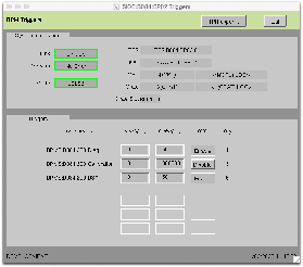
- TPR expert screen
- Verify that the event counts for the enabled channels increments
- Verify the BSA/MPS Acquisition Trigger is enabled and the corresponding channel is enabled
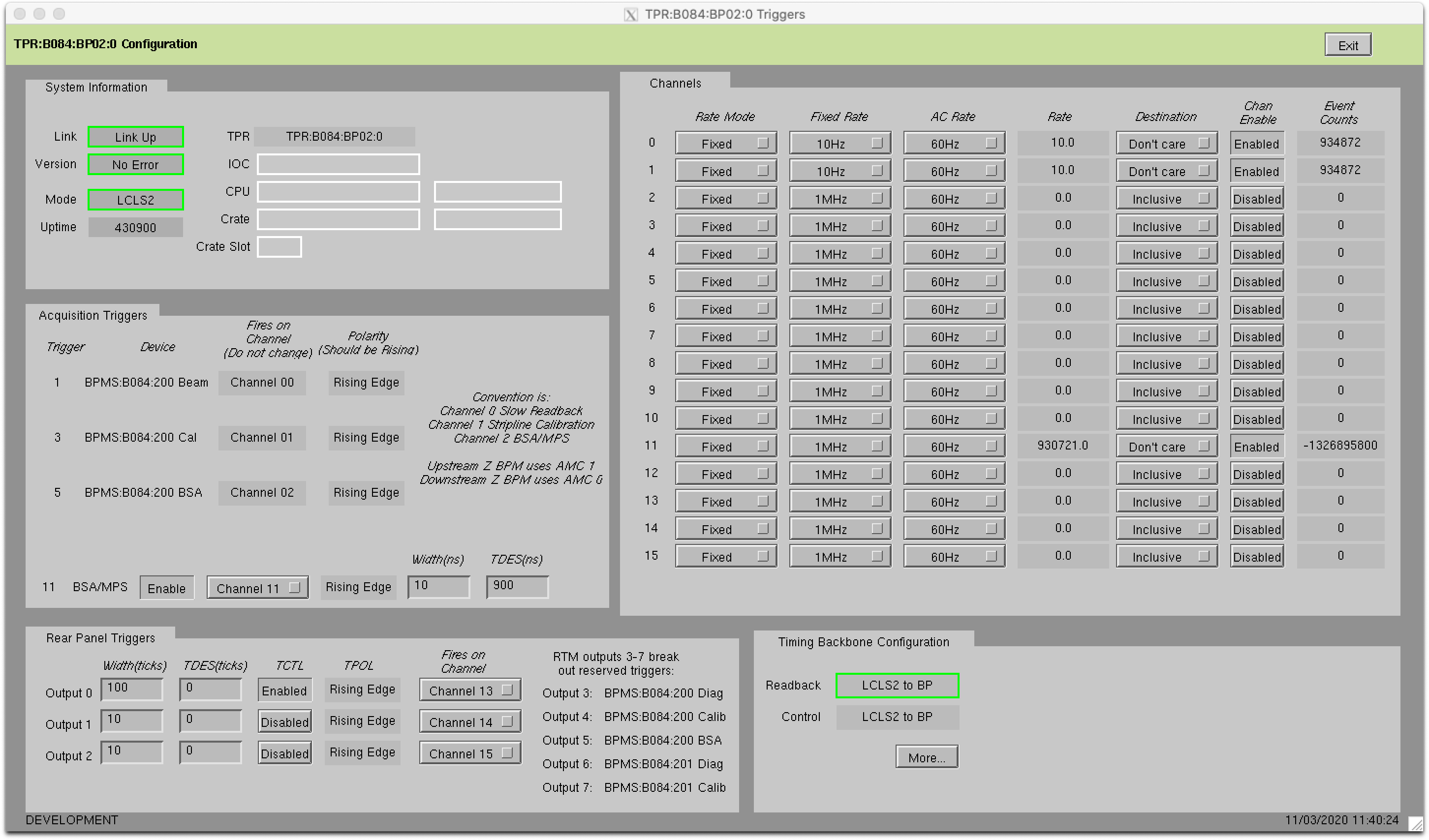
- Verify channel 0 and 1 are enabled with a fixed rate of 10Hz
- Set up your EDEF (Matlab sets up during run):
- NtoAvg - number of shots to average
- NtoAcq - number of samples to acquire
- Set Rate Mode = Fixed Rate
- Set Measurement Severity = Invalid
- Set Destination Mode = Disable
- Set Fixed Rate# to match your trigger rate (typically use [4] 100Hz)
- 0 = 1 MHz
- 1 = 71 kHz
- 2 = 10 kHz
- 3 = 1 kHz
- 4 = 100 Hz
- 5 = 10 Hz
- 6 = 1 Hz
In a Matlab window run bsa_resolution
- Open Matlab
- Source the following if not done
bashsource /afs/slac/g/lcls/epics/setup/epicsenv-7.0.3.1-1.0.bashsource /afs/slac/g/controls/development/package/matlab/setup/matlab_2017b_setup_local.bash
cd /afs/slac/g/lcls/users/BPM/LCLS_II/matlabmatlab &- Run
bsa_resolution.m - Be sure to close Matlab when done
- Change SN inline 6
- Sets to acquire: 2000
- Is the resolution <1.5um in both planes?
7. Calibration Test
- Before starting verify the IOC is not running
- Install 50 ohm terminators on the front end of the board
- Start the IOC
- Refer to the SIOC:B084:BP02 Triggers screen for the calibration triggers status
- Adjust the RF Pulse Width from the RTM:
- caput BPMS:B084:200:RFWD 6
- This sets the RF width to 200ns
- Adjust the attenuators of the board
caput BPMS:B084:200:ATT2 #caput BPMS:B084:200:ATT1 #- I typically do not change this attenuation setting
- caput BPMS:B084:200:CALA #
- Check the calibration calibration in the triggers window)
- CAL RED should have a waveform on the left
- CAL GRN should have a waveform on the right
- CAL TOGGLE should show both the RED and GRN waveforms simultaneously
- CAL signals should be constant, no skipped pulses
- Disconnect the cables from the splitter and connect to oscilloscope
- Verify a 10 dB of attenuation in line on the front of the oscilloscope for the port/ports to be used
- Disable the calibration triggers
- Remove the 50 ohm terminators
- Connect a cable to the red and green input of the AMC and to the scope
- If only using one channel at a time verify calibration triggers are disabled in between switching the channel under test
- Enable the calibration triggers
- Verify calibration toggle is set for only one channel at a time
- Record the Vpp for both green and red channels
Using the 2-slot debug crate
- Start the software:
- log in to lcls-dev3
ssh laci@cpu-b084-sp01- In bash:
Open the UI- open a new lcls-dev3 window
cd /afs/slac/g/lcls/package/cpsw/cpswTreeGUI/current/./env.slac.shpython3 cpswTreeGUI.py --ipAddress=10.0.0.101 --rssiBridge=cpu-b084-sp01 --disableStreams ~disco/scripts/B084_TestStand/stripline_yaml/AmcCarrierBpmStriplineDDV1_project.yaml/000TopLevel.yaml NetIODev&
- Or
~disco/scripts/bash/ControlGUI.sh
- Under the mmio tab "right mouse" click "load file" <default.yaml>
Notes
- Use 300MHz, -5dB to start. Change amplitude as needed. If using a splitter, -2dB is good
- Bay 0 is the left bay, Bay 1 is the right bay
- Attenuator controls are under AppTop -> AppCore -> AmcBayX -> StriplCalCtrl
- 1f = attenuator full-on (lowest/no signal)
- 00 = attenuator full off (highest signal)
- DataValid and RawData are under AppTop -> AppTopJesd[XX] -> JesdRx
- TriggerCount is under AppTop -> DaqMuxV2[X]
- Typical things to check:
- Input capacitors:
- Does the signal show up? Is it significantly lower than other channels?
- Try removing caps on bad channels to see if the signal improves. If not, it's a problem with the SMA connectors.
- Filters:
- Check the top right corner (facing faceplate)- Is the signal less than 80% of the input signal?
- Bad filters have to be sent out for replacing
- Amplifiers:
- U16
- U17
- U21
- U22
- U26
- U27
- U31
- U32
- Remember to change attenuator values, the best are:
- MAKE SURE TO LOOK ACROSS THE CAPS AFTER THE AMPLIFIER
- Compare with a good channel to check that amplifier is working correctly
- ADC Clock Signal:
- R105A/B
- R105 should have a 1.5GHz square wave
185A/B- 185 should have a 370MHz sine wave
- ADC bias along the bottom (for pins 2, 7 and 8)
- Should have [some voltage] CHECK WITH A GOOD BOARD
- Bad ADCs need to be sent out for replacing
- R26 and R27 should have 0V and 8V (or vice versa)
- R?? should have 5V
Programming AMC Carriers
- Log onto lcls-dev3
cd /afs/slac/g/lcls/users/BPM/LCLS_II/BPM/firmware- Run bash script (This will change depending on where you're doing the programming. Check the program to make sure it has the right SHM, slot, and CPU addresses.)
- For the RF lab in B84:
./ProgramBPM_li00_sp01_s3.bash - For Thuy's lab in B34:
./ProgramBPM_CPU_hp05_s3.bash
Useful Commands
Caput [address] value - set a value
Caget [address] value - read a value
Ps -ef | grep ??? - check to see if matlab is hung up/still running
~disco/scripts/bash/bpm_launcher.sh
Other Programs
These programs can be found in ~disco/scripts/python
matViewer
- This can be used to look at the .mat files that were made for running the fake beam test.
- Two files are needed to run:
- 000FileViewer.py
- matplotlib_window.py
- The main window is 000FileViewer.py, this shows all the serial numbers for the found files
- matplotlib_window does what it sounds like, it will show the array that was made from the raw wave and the x y graph.
Graph_Attn_Sweep.py
- This takes the output of the attnsweep program and makes a graph
- it can take two arguments:
- Required: the input file to process
- Optional: an output image
- The program will run with bash invoked and will draw a window on the screen with relevant data in a text box
- This can also be found in /afs/slac/g/lcls/users/BPM/LCLS_II/BPM/software/lcls2-py-scripts