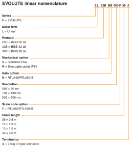
There are two absolute encoders and here is the explanation from Gary: The original design was an actuator with 1 micron repeatability. Harmon specified a linear encoder. An encoder with 50nm resolution was selected. Heinz-Dieter in his PRD stated we needed 250nm resolution. With the linear encoder that resulted in ±5 pulses. Harman said that may be OK, but more pulses would be easier to tune. He suggested the AksIM-2 rotary encoder. I selected 17 bit resolution. That results in 131,072 counts per 500 microns, or .0038147 microns/pulse, approximately 66 pulses/250nm. This may be easier to tune. I put both encoders in this version of the actuator to experiment with both, to determine if one or the other could do the job, or if both are required.
Travel range of each actuator
5 mm (+/- 2.5 mm)
Lead screw pitch
0.5 mm/rev
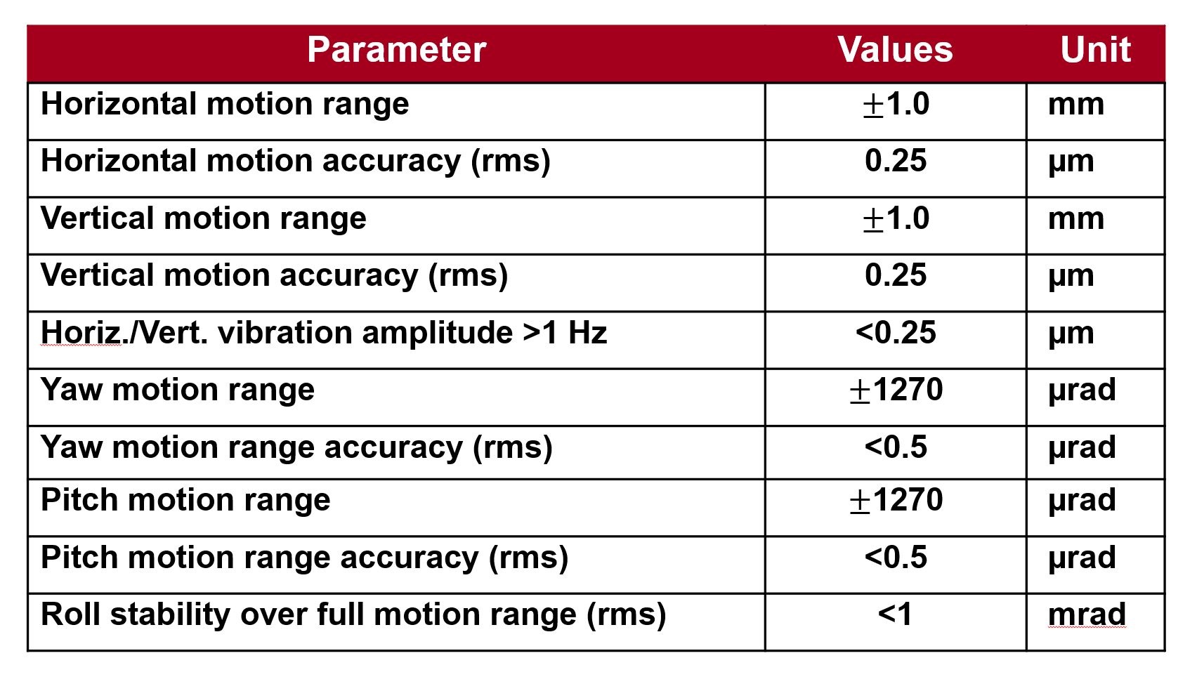
Required positioning accuracy
0.25 um
Gear reducer
Phase 1 CMM Test:
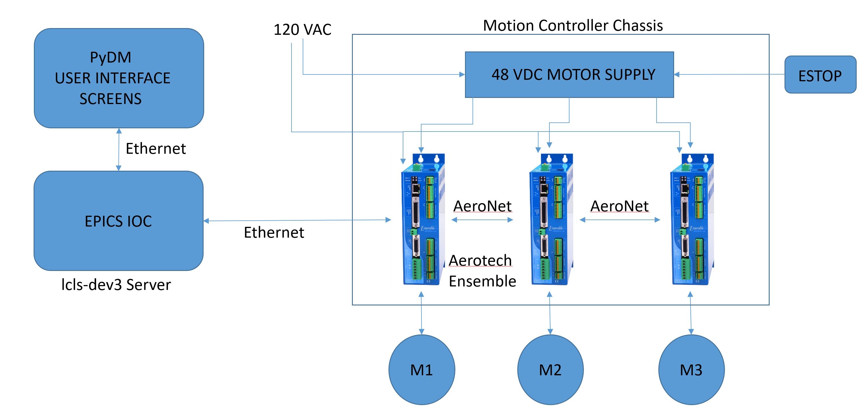
- There are two vertical actuators and one horizontal actuator with an opposing tensioning spring
- A control system for the three linear actuators and linear encoders plus the optical measurement system will be needed for the phase 1 tests
- These controls will later be integrated into the LCLS accelerator control system
- The entire assembly shown in Figure 3 will be placed on a coordinate measuring machine (CMM)
- This will allow the linear encoder positions in the actuators, and the optical position readback to be verified with the CMM data.
- The linear encoders and optical displacement measurement system is designed for submicron resolution, an order of magnitude better than the CMM system measurements
- by plotting the data over a ±3 mm range of motion and calculating a line of best fit we expect to be able to conclude that the device resolution has been achieved.