Introduction:
The Optoboard System is the data aggregation and signal conversion stage of the ATLAS ITk Pixel data transmission chain. The basic working principle is:
- DATA: 6x 1.28 Gbps electrical links from the front-end modules are serialized into 1x 10.24 Gbps optical link and transmitted to the backend (FELIX).
- CMD: 1x 2.56 Gbps optical link with trigger and command are deserialized into 8x 160 Mbps electrical links and transmitted to the front-end (ITkPix). Also the Optoboard gets controlled through the optical link.
One Optoboard consists of:
- 4 lpGBTv1: one as a master available through IC, three as slaves controlled through I2C controller of the master. Manual/description here.
- 4 GBCR2: all controlled through lpGBT master I2C controller. Manual here.
- 1 VTRx+: controlled through lpGBT master I2C controller. Description here.
- 1 bPOL2V5 carrier board: houses the bPOL2V5 ASIC that converts 2.5 V to 1.2V. Datasheets here.
Specific for SLAC's test-Optopanel will be marked in red .
Mechanics:
- Up to 8x Optoboards are housed in one Optobox. One Optobox consists also of:
- 1 Powerboard: hosts 5 bPOL12V ASICs (conversion 9 V to 2.5 V) and 1 MOPS chip
- 1 Connectorboard: handles power distribution form the 5 bPOL12V to the 8 Optoboards according the SP chain powering/detector layout.
- Up to 28x Optoboxes (14x normal, 14x mirrored) are housed in one Optopanel.
- Each side of the ITk has 4 Optopanels.
Currently specific for SLAC IS demonstrator:
4x Optoboard V2.1 are housed in one Optobox. This Optobox is housed in a Test-Optopanel.
Interfaces:
Please refer to our Interface Document here. All the connectors of the Optoboard System is explained there.
Adapter boards:
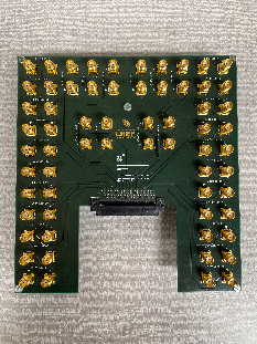
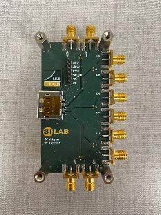
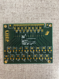
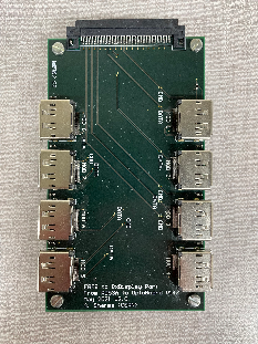
| ERF-SMA (routing, schematics) from Bern | DP-SMA (routing, schematics) | ERF-twinax from Bern | ERF-8x DP (routing, schematics) |
|---|---|---|---|
|
|
|
|
Schematics:
All schematics for all of Berns designed PCBs can be found here.
Optoboard system support:
We collect support requests and general questions on our Mattermost channel Bern-Optoboard (invite link). Your contacts as of Aug. 2022 are Aaron O'Neill and Daniele del Santo.
Optoboard software for FELIX:
We created a repository with scripting software to easily configure the Optoboard: https://gitlab.cern.ch/bat/optoboard_felix. A lot is documented in the readme and wiki of the repository.
The repository is located in the directory:
/home/itkpix/optoboard-system
To configure an Optoboard V2.1 with the default configurations found simply run these scripts:
In a first terminal felixcore:
cd /home/itkpix/felix-sw/flx-sw-2022-08-11    # or another felix-sw version
source setup.sh
x86_64-centos7-gcc11-opt/felixcore/felixcore -d 0 --data-interface lo --elinks 0,4,8,12     # starts felixcore, check your links!
Note that the elinks might change according your connectivity scheme. More information from Ismet here.
In a second terminal do:
source flx_opto_setup.sh     # if FELIX server restart or stuck: source flx_opto_setup_fresh.sh
cd optoboard_felix
python quick_start.py -v 1.3 -s 00000000 -G 0 -d 0
The -s specifies the serial number used (00000000 is the default one for Optoboard V2.1), -G is the link number of FELIX and -d the FELIX device. If -s is set to 00000000 and -v 1.3, optoboard_felix sends the parameters in the config ~/optoboard_felix/configs/optoboard_lpgbtv1_gbcr2_vtrxv1_3_default.json to the lpGBTs, GBCR and VTRx+. Check the FELIX documentation or the optoboard_felix readme for more information on this.
If you do flx-info link you should see that respective link aligned. If you do flx-info podpower you should see something like this (if single Optoboard outside test-Optopanel is connected similarly):
Optical power (Receive=RX or Transmit=TX) of channel in uW:
        |     0   |     1   |     2   |     3   |     4   |     5   |     6   |     7   |     8   |     9   |    10   |    11   |
        |=========|=========|=========|=========|=========|=========|=========|=========|=========|=========|=========|=========|
 1st TX |  983.30 |  986.10 |  892.10 |  970.00 |  937.50 | 1009.70 |  916.20 |  970.30 |  920.00 |  960.80 |  924.40 |  958.50 |
 1st RX |  946.80 |  790.20 |  870.50 |  761.80 |    0.00 |    0.00 |    0.00 |    0.00 |    0.00 |    0.00 |    0.00 |    0.00 |
After fibre fanout installation:
After the fibre fanout is installed, configuring the Optoboards will look similar to this:
python quick_start.py -v 1.3 -s 00000000 -G 0 -d 0
python quick_start.py -v 1.3 -s 00000000 -G 4 -d 0    # note that -G 1,2,3 are taken by the lpGBT slave fibres
python quick_start.py -v 1.3 -s 00000000 -G 8 -d 0
python quick_start.py -v 1.3 -s 00000000 -G 12 -d 0
Or with the separate configs that are created in ~/optoboard_felix/configs:
python quick_start.py -v 1.3 -c /configs/2400003.json
python quick_start.py -v 1.3 -c /configs/2400003.json
python quick_start.py -v 1.3 -c /configs/2400007.json
python quick_start.py -v 1.3 -c /configs/2400011.json
Note that in this case the connected FELIX fibre channel has to be set inside the configuration file as described in the readme here.
In a currently ongoing effort by Bern PhD student Daniele dal Santo, the software will be integrated into the ITk demonstrator software itk-demo-sw.
Further tools:
flpgbtconf: FELIX low level tool to communicate with (and only with) the lpGBT master directly. flpgbtconf -h will give you help on the tool, here an example:
flpgbtconf -1 -I 0x74 -G 0 -d 0 ULDATASOURCE5_DLG0DATASOURCE 0x1 # sets CMD from data to PRBS7 pattern on EPTX00 and EPTX02
-I 0x74 is the address for the lpGBT and the option -1 for the lpGBT version 1. Consult the lpGBT manual for all the various register names. There are many more options with FELIX, consult the FELIX user manual.
Test-Optopanel at SLAC:
The test-Optopanel houses one Optobox with 4 Optoboards. It has a twinax inlet (round) and a fibre outlet (rectangle). The Optobox is mounted on a cooling plate with two 8 mm pipes. The
A collection of photographs from the test-Optopanel and its sister at CERN SR1 can be found here. See also this Twiki here of the SR1 test-Optopanel which has similiar information (but some very different configurations).
Optoboards:
| slot: | OB1 | OB2 | OB3 | OB4 | OB5 | OB6 | OB7 | OB8 |
|---|---|---|---|---|---|---|---|---|
| serial: | 2400006 | - | 2400003 | - | 2400007 | - | 2400011 | - |
| powering from bPOL: | A | A | B | B | C | C | D | D |
| idle current* [mA] | 182 | - | 165 | - | 168 | - | 174 | - |
| FELIX link: |
*after power-up and inside the test-Optopanel with 9.0 V supplied. If powered outside the test-Optopanel directly on the connector with 2.5 V expect a current ~415 mA.
Connectors:
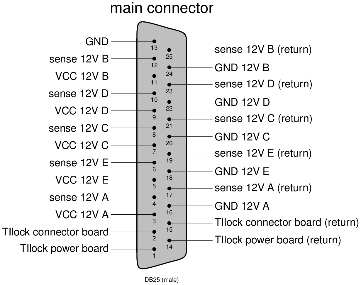
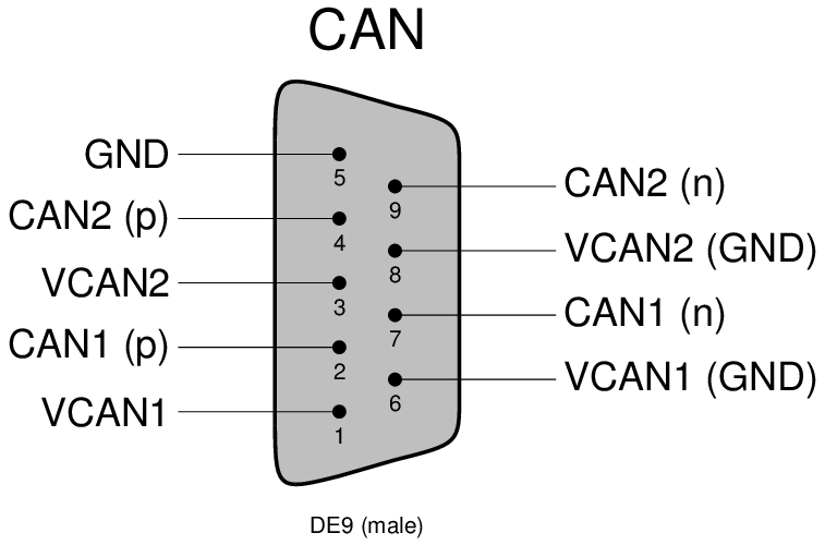
Check the above interfaces document for more detailled description.
Banana plugs are labelled according to powered bPOL12V.
Cooling and dry air inlet/outlet: FESTO 8 mm
DCS:
Currently no MOPS is mounted on the Powerboard inside the test-Optopanel (due to availability). We will ship one as soon as we got our hands on them.