BSA and MPS data are passed from the LCLS2 LLRF system to the LCLS2 Common Platform by fiber link. The SRF cavity I&Q are calculated within the LLRF PRC chassis for 4 cavities. The severity of the BSA quantities is determined and assigned within the PRC indicating if the the data is "good" The I&Q data properly represents the state of the cavity field (SEVR = 1,1) The I&Q data does not properly represent the state of the cavity field, e.g. PLL loss of lock (SEVR= 0,0). The LLRF MPS status for the 4 cavities is also collated within the PRC. These data are packaged, with a global time stamp, and passed over the fiber link at a repetition rate of 1 MHz. The structure for data generated by 1 PRC is shown in Figure 1.
Within the structure from 1 PRC, there are 12 BSA Severity tags each with 2 bits. The severity flag will indicate if the associated cavity BSA quantity is "good" and should be evaluated as such. At this time, the LCLS2 LLRF system developers have not determined a case where data should be considered invalid. The severity for each 32 bit quantity is expected to contain two bits = 1 for valid data.
Within the structure from 1 PRC there are 12 BSA Quantities. Currently 8 of 12 quantities are defined. The BSA Quantity descriptions are shown in Figure 1, along with the associated severity for each quantity.
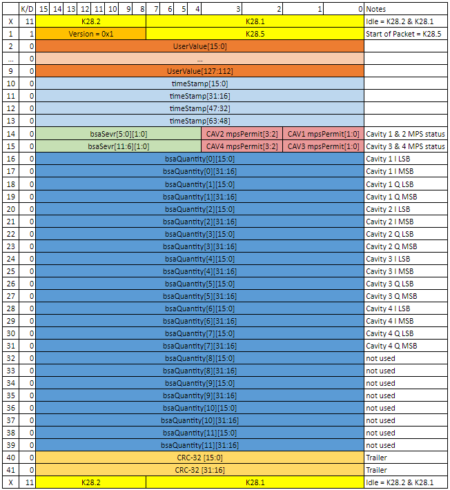
Figure 1: BSA / MPS datastream sctucture
Within the structure from 1 PRC, there are 2 groups of 4 MPS status bits, and 12 BSA Quantities 32 bits long. Each SRF cavity corresponds to two MPS bits which allow for 4 states per cavity as described in figure 2
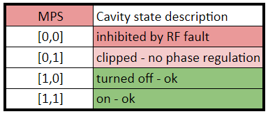
Figure 2: MPS states for LLRF cavities
Each LLRF rack passes BSA and MPS data for 4 cavities over a single fiber connecting the LLRF PRC chassis to an AMC . As built, four PRCs are connect to each AMC through four separate fiberoptic cables. Each AMC fits with an AMC Carrier slot, such that each AMC Carrier contains 1 AMC Card and 1 AMC filler card. As a result, each AMC Carrier is processing MPS and BSA data for 4 PRCs, a total of 16 SRF cavities.
An example of the LLRF to AMC Carrier installation for LCLS2 is provided in Figure 3. For every cryomodule, there are 4 LLRF PRCs connected to 1 AMC. There is 1 AMC Carrier to process MPS/BSA data for 16 SRF cavities. The mapping demonstrates that each AMC carrier will have at least 32 quantities of 32 bit BSA data available for mapping to the LCLS2 diagnostic bus.
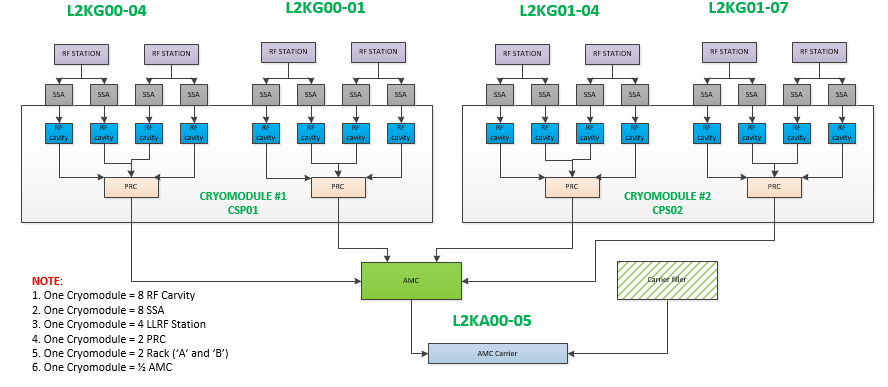
Figure 3: LLRF -> AMC Carrier distribution example, as built. Each AMC Carrier has 2 slots, one of which is filled by an AMC card, the other is filled by an AMC filler card (not a second AMC Card).
Data structure, repetition rate, and resolution
The LCLS2 BSA diagnostic bus has been designed to process data at a repetition rate of 1 MHz, the full rate of the LCLS2 beam. This repetition rate is built into the AMC firmware.
The total allotment of space per AMC Carrier for BSA quantities mapped to the diagnostic bus is 24 quantities of 32 bits. This requires that the total package of 48 quantities of 32 bit data from the LLRF system be appropriately condensed to fit within the defined structure of the diagnostic bus. This is achieved by dropping the 16 Least Significant Bits (LSBs) and retaining the 16 Most Significant Bits (MSBs) in the AMC Carrier firmware.
As it is mapped to the diagnostic bus, RF BSA data is structured to fit within a standard block of 24 BSA quantities of 32 bits per 1 MHz cycle.