Installing the Touch Panel
- Mounting and Connecting to Power
- The C-more touch panel order with come with the touch screen, mounting clips, and a terminal block.
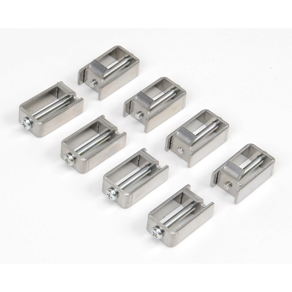
- Use the mounting clips (pictured below) to secure the panel, from the inside, to LSS box door.
- Secure terminal block to back of panel.
- Connect one black wire (GND) from the ground terminal to grounded contact on rack.
- Ground terminal is second from the bottom and will be labelled with the ground symbol.
- Connect one blue wire (power) from the negative terminal to 24V contact on rack.
- Negative terminal is third from the bottom and will be labelled with a minus sign.
- Connecting to the PLC
- Connect HDMI cable from 15-pin port on back of panel to Data Communications Module port (pictured below).

- Connect HDMI cable from 15-pin port on back of panel to Data Communications Module port (pictured below).
- Connecting to Computer
- To upload new code, connect USB Cable from port on back of panel to port on computer.
Installing C-more
- Download the C-more software
- https://www.automationdirect.com/support/software-downloads?itemcode=C-more%20EA9%20Series
- NOTE: some existing LSS still use EA7
- License Key: 7UGA-R9M6-3FKY-6TQV
- https://www.automationdirect.com/support/software-downloads?itemcode=C-more%20EA9%20Series
- Connect to the PLC
- In C-more, go to Setup > Panel Manager.
- Choose the panel type as labelled on the back of the panel.
- Under COM Port1, click DEV001
- PLC Protocol: AutomationDirect Modbus
- Baud Rate: 9600
- Parity: odd
- Stop Bit: 1
- Transfer a program to the panel
- File > Project Transfer... > Transfer
- Or click the "Send" icon at the top of the window
Programming Common Objects
- General
- Choose objects from Object Library on right-hand side of screen
- Or use "Object" drop-down menu at top of screen
- Example LSS Touchscreen.pdf
- Example LSS Touchscreen.eap
- Choose objects from Object Library on right-hand side of screen
- Tag Names
- Used to link an object with a variable in the DirectSoft code
- Add tag names
- Navigate to the toolbar and select the drop-down menu labelled "Database"
- Click "Tag Name Database..."
- Click the "Add" icon at the top of the pop-up window
- Device Name = DEV001
- In the "Tag Name" entry box, type the desired nickname
- Tag Data Type = Discrete
- Select Memory Type from drop-down menu
- C variables are internal
- X variables are physical inputs
- Y variables are physical outputs
- V variables are used for loading bits into
- Enter address
- Make sure this matches the variable in DirectSoft
- Click "Add"
- Buttons
- Pushbuttons are used to toggle variables between on and off.
- Usually linked to an X variable.
- Use different background colors to differentiate between a button's on and off states.
- Indicators
- Indicator lights are used to display variable status.
- Usually linked to a Y variable.
- Multi-State Text Indicator
- Used to display laser mode status and error messages
- Choose "Message" tab at top of pop-up window to add message
- Click "Add New"
- Type message into text box
- Choose background color
- Bit No. is assigned automatically
- May be loaded into V memory space in code
Each bit corresponds to a K value:
Bit K-Value 0 1 1 2 2 4 3 8 4 10 5 20 6 40 7 80
- Screen Selector
- Used for menu to toggle between pages
- Insert at bottom of new screen