Intro
The XRT had several disabled axes and nearly broken chassis that were causing all kinds of hackery and finagling for ops as a result of rushed commissioning. To make things better we decided to go through each chassis 1 by 1 and fix outstanding issues, enabling all axes, including bending. This post goes over what was fixed and changed, and why.
Objectives
- Enable all axes
- Fix all chassis
- Fix all cables
- Verify motion
- Verify all drive settings and capture on google drive
- Improve gantry tuning and control
- Misc improvements
Enable all the axes
I made a benchtesting procedure, while verifying the first chassis myself. I then trained Ivan on how to verify chassis on the bench and field. He then worked independently with Danh Du to complete the checkout for M3. Danh then completed the verification for M2 installation with May Ling.
With each verified chassis we had a solid reference for finding mistakes in cables. A loose wire on the bender motor cable for M1 was discovered. Other errors in the chassis were discovered during benchtesting. Sorting out the problems after chassis installation would have been painful (that's what we tried to do originally).
Ivan's Notes:
HOMS Chassis Bench testing Procedure
https://www.evernote.com/shard/s195/sh/2e401b24-a72c-4533-b743-82b4eb325ade/af309bb3f42be622
XRT HOMS M1 work log:
XRT HOMS M3 work log:
XRT M3 HOMS ELMO CHASSIS work
Bench test Chassis #1805527 (originally installed in XRT M3)
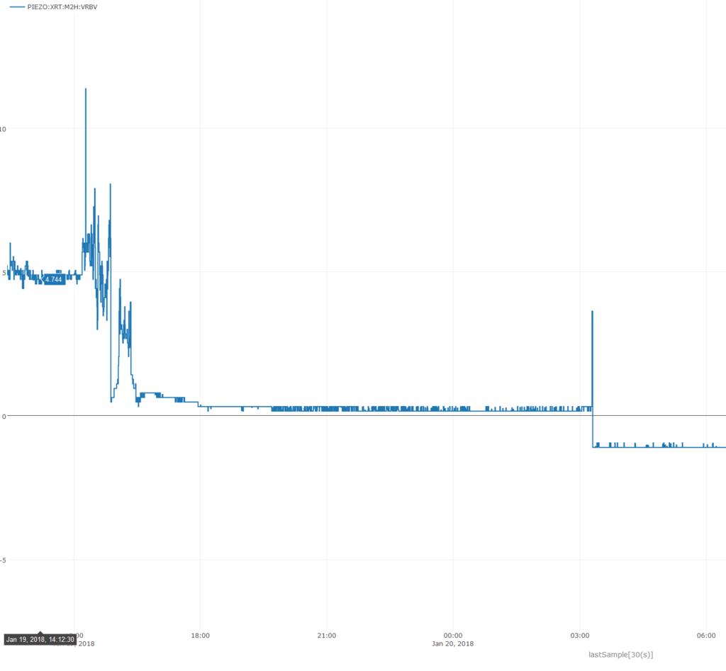
A dead piezo!
While recommissioning all the XRT HOMS we encountered a piezo failure on M2H. For no apparent reason the piezo died, and we had to scramble to replace it. Actually Corey and Daniele replaced it, while Teddy and I completed verification of all other axes. We don't understand why it failed. Here's the voltage from when it failed:
Improve gantry tuning and control
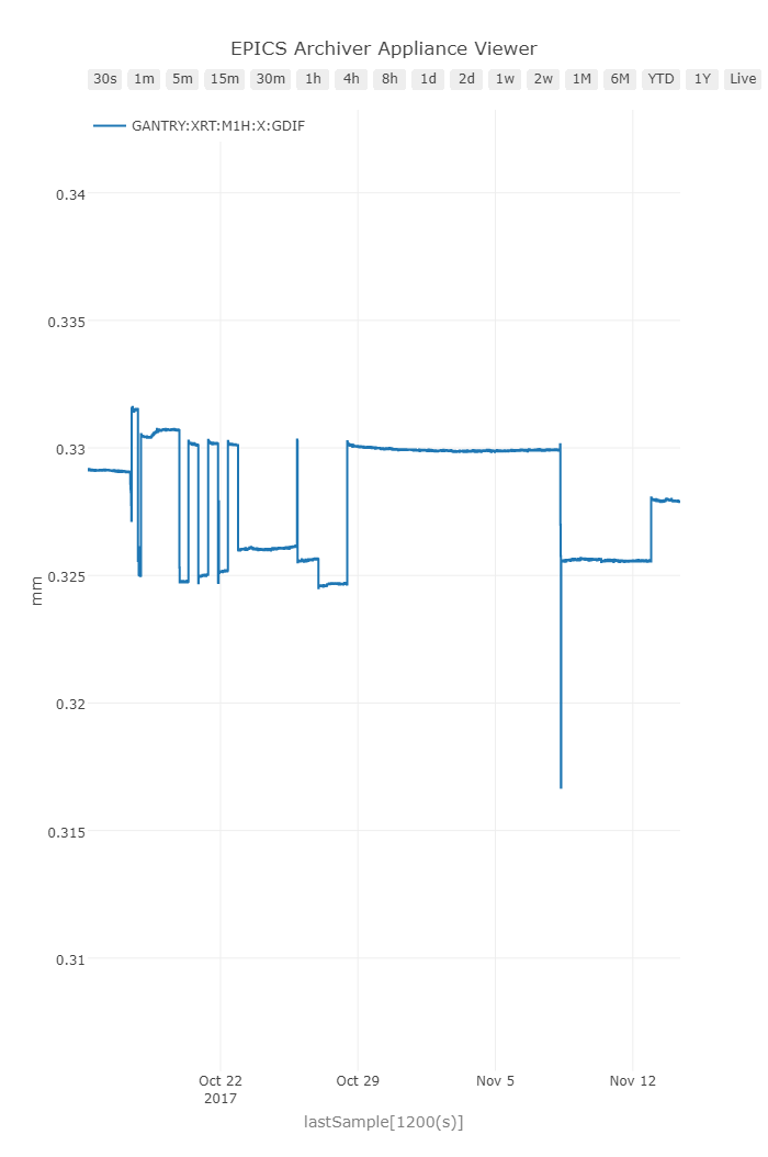
Problem
When moving the axes in gantry a gantry difference would accumulate over time. This would ultimately lead to a parasitic pitch. Each axis would move in-sync pretty well, but it might give up moving before it actually reached a final target, and each drive would give up on its own. This lead to a gantry error that would vary between +/- 10um. Not very good for pointing to 30nrad!
Solution
Each gantry axis had a large settling window, and extremely short settling time. By adjusting in the direction of perfection the axes were able to settle a bit more, leading to a more accurate final position. Additionally, by setting the holding current to something other than zero (0.5 A) the axes would also compensate for any other drift and maintain a sharp encoder position. Now the only concern is any heat making its way into the rest of the system. We'll see how that turns out!
Results
After some testing we found that the gantry error was being maintained over several moves to <1um. A significant improvement.
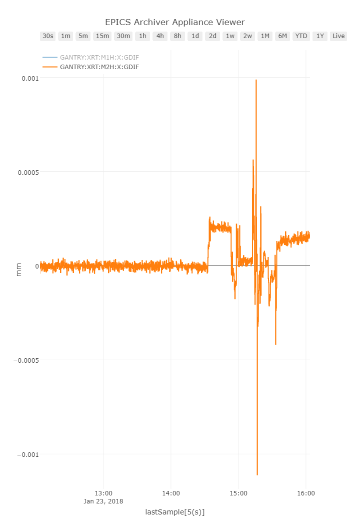
Oops, looks like there is some weird drift there... Turns out when we added some guards for position lag monitoring they tripped the axes off due to some rough handling of the mirror enclosure. Resetting the axis did the trick:
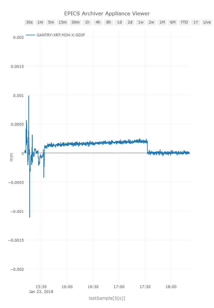
But this means we need to implement the EPICS interface for resetting such faults easily, and diagnosing the problems.
Miscellaneous Improvements
EtherCAT Sync Groups
What are they?
EtherCAT frames have a working counter (notice WC anywhere?) variable that is decremented by 1 for each slave in a sync-group. The idea being, if any of your interfaces on the ethercat network aren't reachable, or there is some other problem, the working counter will be > 0 when it reaches the master. The master then invalidates the entire bus, moving all of the ethercat devices to a non-operational state. Usually if there is a problem with the bus, the slaves downstream of the problem will notice, but any slaves upstream of the problematic one will not know, so the master must tell them something is wrong. That's why we have the working counter. Also the PLC code pays attention to the working counter (when it is programmed well), and state machines will go to a safe state if the WC > 0.
You can configure your ethercat bus to include different slaves in different sync groups. This makes your design robust against functionally separate faults. We can essentially create firewalls in our ethercat bus, so if one branch of our topology has troubles, others remain functional. For the HOMS this means we can assign branch 1 to M1, branch 2 to M2, and branch 3 to M3. If any of the branches have an issue, only that branch will be affected. The other branches will continue to run.
Application to the HOMS
To set this up you have to have a star network. I designed the HOMS PLC to use this topology. Each EK1122 gives two branches apart from the default line. Two EK1122 in the XRT config is overkill but whatever.
Open up the IO tree and look for the SyncUnits item:
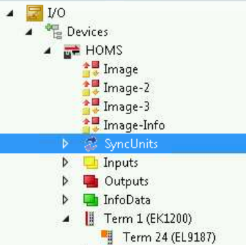
Expanding the item shows the sync groups I established:
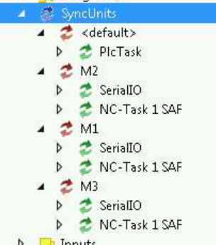
One for each mirror. Selecting M* shows the devices in the sync group in the left hand pane:
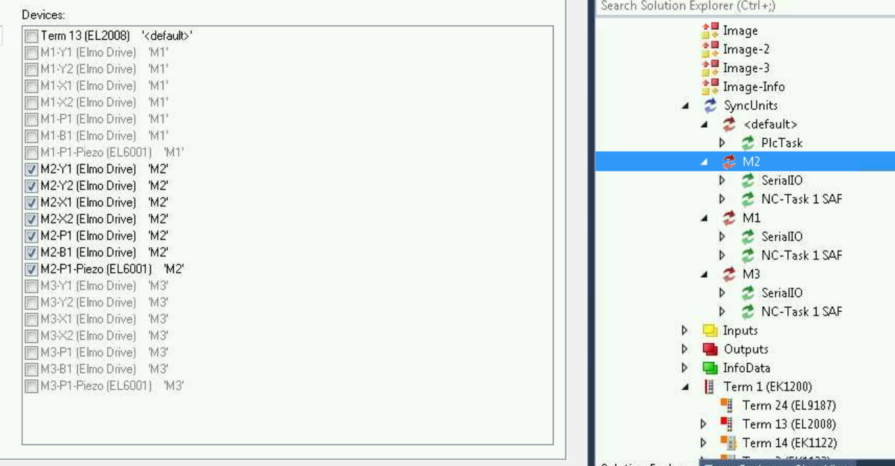
Only devices in <default> can be added to a sync group.
Once this is done the XRT HOMS will be more robust, it would be inexcusable if M1 or M3 took down M2 operations and visa versa.
Overview
Content Tools