Search/Navigation:
Related:
SLAC![]() /EPP
/EPP![]() /HPS Public
/HPS Public![]()
Jefferson Lab![]() /Hall B
/Hall B![]() /HPS Run Wiki
/HPS Run Wiki![]()
S30XL-LESA/LDMX
The following DAQ map is based on the projected cable lengths and planned mechanical layout.
| Front End Board (FEB) ID | FEB Hybrid ID | SVT Layer | Half-Module Layer* | Orientation | Volume |
|---|---|---|---|---|---|
| 0 | 0 | 1 | 1 | Axial | Top |
| 0 | 1 | 1 | 2 | Stereo | Top |
| 1 | 0 | 2 | 3 | Axial | Top |
| 1 | 1 | 2 | 4 | Stereo | Top |
| 1 | 2 | 3 | 5 | Axial | Top |
| 1 | 3 | 3 | 6 | Stereo | Top |
| 2 | 0 | 4 | 7 | Axial | Top |
| 2 | 1 | 4 | 7 | Axial | Top |
| 2 | 2 | 4 | 8 | Stereo | Top |
| 2 | 3 | 4 | 8 | Stereo | Top |
| 3 | 0 | 5 | 9 | Axial | Top |
| 3 | 1 | 5 | 9 | Axial | Top |
| 3 | 2 | 5 | 10 | Stereo | Top |
| 3 | 3 | 5 | 10 | Stereo | Top |
| 4 | 0 | 6 | 11 | Axial | Top |
| 4 | 1 | 6 | 11 | Axial | Top |
| 4 | 2 | 6 | 12 | Stereo | Top |
| 4 | 3 | 6 | 12 | Stereo | Top |
| Front End Board (FEB) ID | FEB Hybrid ID | SVT Layer | Half-Module Layer* | Orientation | Volume |
|---|---|---|---|---|---|
| 5 | 0 | 1 | 1 | Stereo | Bottom |
| 5 | 1 | 1 | 2 | Axial | Bottom |
| 6 | 0 | 2 | 3 | Stereo | Bottom |
| 6 | 1 | 2 | 4 | Axial | Bottom |
| 6 | 2 | 3 | 5 | Stereo | Bottom |
| 6 | 3 | 3 | 6 | Axial | Bottom |
| 7 | 0 | 4 | 7 | Stereo | Bottom |
| 7 | 1 | 4 | 7 | Stereo | Bottom |
| 7 | 2 | 4 | 8 | Axial | Bottom |
| 7 | 3 | 4 | 8 | Axial | Bottom |
| 8 | 0 | 5 | 9 | Stereo | Bottom |
| 8 | 1 | 5 | 9 | Stereo | Bottom |
| 8 | 2 | 5 | 10 | Axial | Bottom |
| 8 | 3 | 5 | 10 | Axial | Bottom |
| 9 | 0 | 6 | 11 | Stereo | Bottom |
| 9 | 1 | 6 | 11 | Stereo | Bottom |
| 9 | 2 | 6 | 12 | Axial | Bottom |
| 9 | 3 | 6 | 12 | Axial | Bottom |
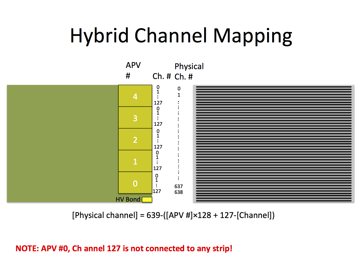
EPICS Channel Mapping
Following the DAQ channel ordering and the sensor strip channel numbering the conversion between the two is summarized below.