Trigger setup
The external trigger for the CU acquisition is a combination of signals coming from the accelerator cycle, several scintillators and cerenkov counters placed in the experimental area.
Standard Trigger Configuration
Below is a picture of the trigger logic and a description of the elements needed to set the standard trigger configuration.
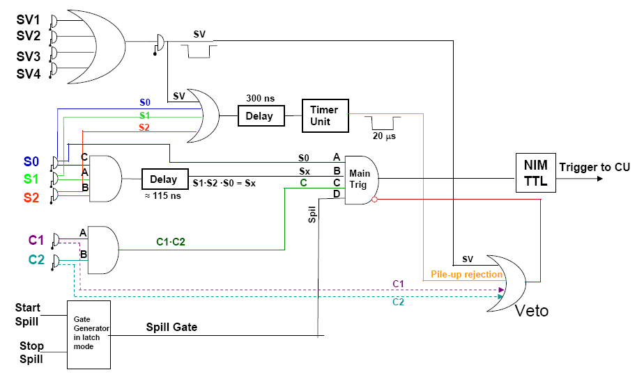
- SV1, SV2, SV3, SV4: veto scintillators 41cm × 20.4 cm × 1 cm
- S0: 41cm × 20.4 cm × 1 cm
- S1: 2cm × 2cm × 2mm
- S2: 4cm × 4cm × 2mm
Note
Cherenkovs in the trigger: To include the Cherenkov counters in the trigger push the C switch in the main trigger section in the coincidence unit. Check that the Cherenkov discriminator threshold is set to TBD mV.
Trigger with Cherenkovs in veto: To set the trigger with the Cherenkov counters as veto, unselect the C switch from the main trigger section in the coincidence unit and plug the C1 and C2 unplugged cables (labeled C1 veto and C2 veto) from the discriminator into the second section from the top of the Logic fan-in fan-out (4th module from the left). The Cherenkov discriminator threshold must be set to TBD mV.
Trigger Configuration for pile-up study
This configuration allows to collectd in the same run a beam particle event ("true") followed by an junk event ("fake").
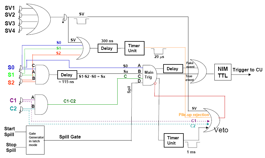
Istructions to change from the standard configurations to the configuration to study pile-up
1. Remove the "CU cable" from the NIM/TTL module and plug it into the LOGIC FAN IN/OUT (3rd section from the top with white label)
2. Plug the output "EXT + FAKE" cable into the NIM/TTL module
3. Plug the "Veto gate" cable into the "OR VETO" LOGIC FAN IN/OUT (2nd section 2 from the top with black label)