Proposal for precise geometry parametrization of planar imaging detectors.
Content
Coordinate system at interaction point
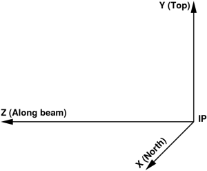
In most experiments the Cartesian coordinate system of setup is defined by the 3 mutually orthogonal right-hand-indexed axes with origin in the interaction point (IP) of the photon beam with sample:
Tile ideal geometry
- Assume that the detector image is produced by a set of tiles (a.k.a., segment, section, 2x1, sensor, Si-pixel matrix, etc).
- Each tile has well defined by design geometry of pixels, which does not need in separate calibration.
- Pixel (x,y) center coordinate at z=0 for each tile can be defined as a look-up table in its "natural" matrix-style coordinate system.
- For example, CSPAD 2x1 tile pixel geometry is defined as
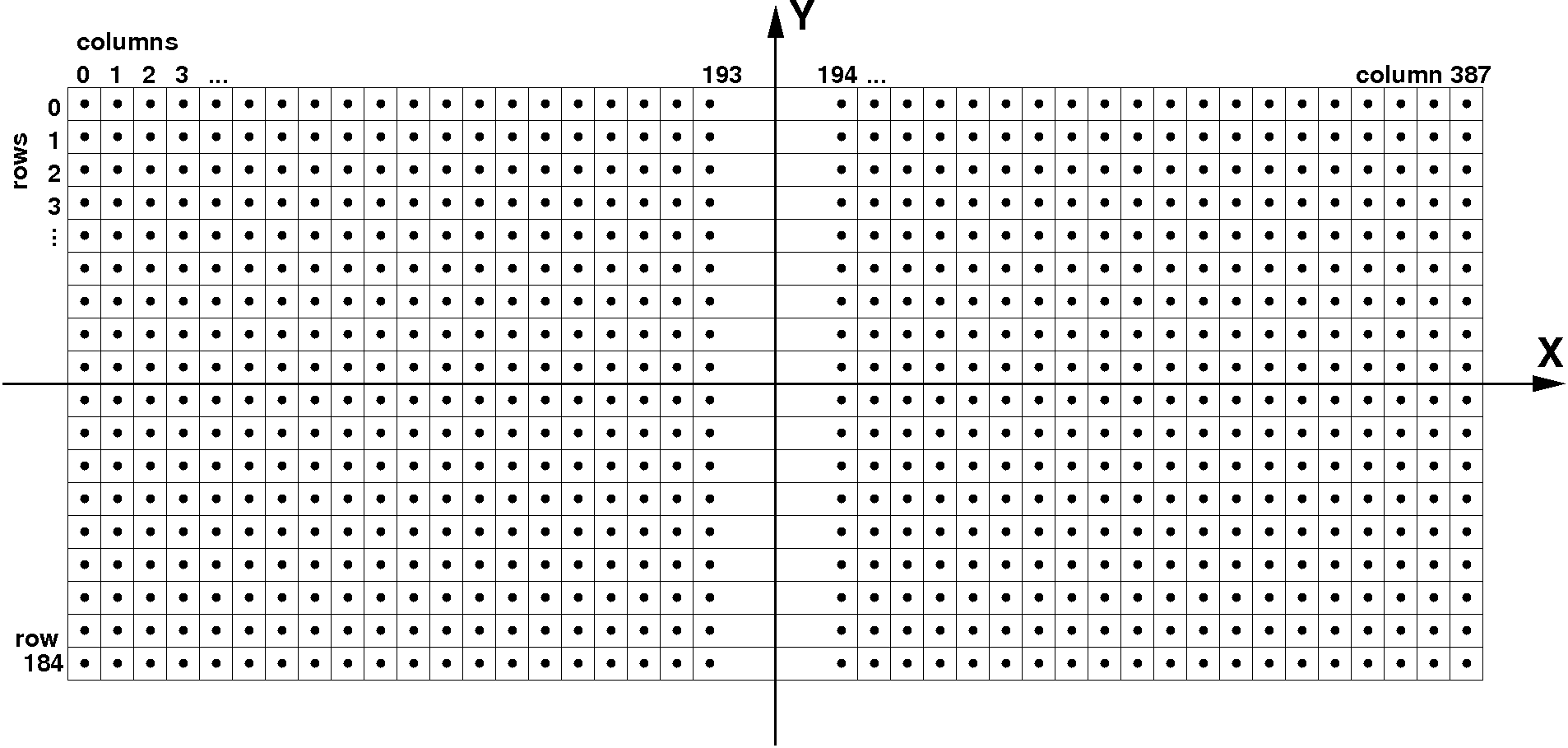
- Regular pixels have size is 109.92 x 109.92 µm2,
- Pixel size in two middle columns 193 and 194 is 274.80 x 109.92 µm2.
Memory model
It is assumed that each tile is presented in DAQ or offline data by a single block of memory. Uniform matrix-type geometry of pixel array is preferable, but other geometry can be handled, for example like in CSPAD 2x1 sensor. Detector data record consists of consecutive tile-blocks, in accordance with numeration adopted by DAQ. For effective memory management, some of the tile-blocks may be missing due to current detector configuration. Available configuration of the detector tile-blocks should be marked in a bit-mask word in position order (bit position from lower to higher is associated with the tile number in DAQ).
For example, consecutive pixel index in the CSPAD 2x1 tile memory block of size (185,388) is
i = col + row*388.
Optical measurements
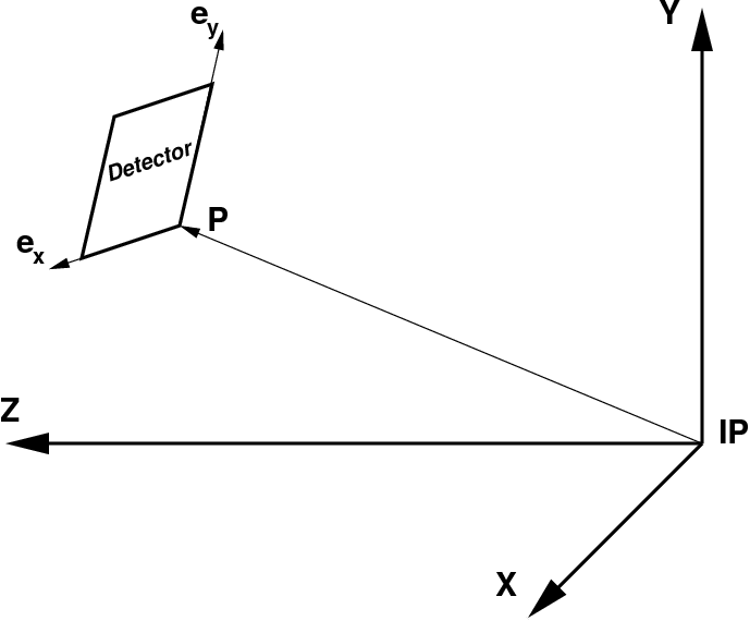
- Optical measurements provide 3-d coordinates of 4 corners for all tiles in the detector in some arbitrary microscope plane which coincides with detector imaging array (tiles) plane within precision of installation.
- Tile corner coordinates do not necessarily coincide with corner pixel centers or edges.
- Numeration of tiles should not necessarily coincide with their numeration in DAQ, but it should be done in fixed order or with indication of tile numbers:
Optical measurements provide a list of coordinates for all sensor points:
Tile # Point # X[µm] Y[µm] Y[µm]
Quality check
Quality check of optical measurement may include for each tile:
- equity of opposite sides
- equity of diagonals
- equity of tilt angles for all sides
- tile flatness in 3-d
Position of tiles in the detector
Detector pixels' geometry in 3-d can be unambiguously derived from
- the list of coordinates obtained in optical measurements,
- tile ideal geometry, and
- designed orientation of tiles in the detector.
The tile location and orientation can be defined by the table of records
| Tile # | Xc[µm] | Yc[µm] | Yc[µm] | Rotation angle [degree] | Tilt in X-Y[degree] | Tilt in Y-Z[degree] | Tilt in X-Z[degree] |
|---|
where
- Tile # – Tile number in DAQ
- Xc, Yc, and Zc[µm] – tile center coordinates in micrometers
- Rotation angle [degree] – tile rotation angle in X-Y detector plane in degrees, presumably it is N*90, where N=0,1,2,3
- Tilt in X-Y, Y-Z, X-Z[degree] – small angles for correction of the tile orientation w.r.t. design rotation angle
Tile center coordinates are defined as an average over 4 corners.
Tilt angles are projected angles of the tile sides on relevant planes. Each angle is evaluated as an averaged angle for 2 sides.
Summary
Suggested method for imaging detector geometry description provides simple and unambiguous way of pixel coordinate parametrization. This method utilizes all available information from optical measurement and design of the detector and tiles. All geometry parameters are extracted without fitting technique and presented by natural intuitive way.
Overview
Content Tools