The controls camera viewer can be run as:
/reg/g/pcds/controls/pycaqt/pulnix6740.latest/run_pulnix.csh --instrument HUTCH --pvlist CONFIG --camera NUM
HUTCH is one of the standard hutch names (fully capitalized), CONFIG is a viewer configuration file, and NUM is an optional parameter telling which camera number to view initially (defaulting to zero).
The Configuration File
The configuration file contains a list of cameras that the viewer can display. Any line that begins with '#' is a comment, and any other line contains either 4 or 5 comma-separated fields with the following information:
- The camera type: one of the reserved words "LIF", "AVG", or "IC". These words do not refer to the actual type of the camera, but the structure of the IOC that supports it. The three types of IOC currently supported are:
- "LIF" is a camera with an image PV named "LIVE_IMAGE_FULL". The number of columns is given by a PV called "N_OF_COL" and the number of rows is given by the PV "N_OF_ROW".
- "AVG" is an "LIF"-type camera that supports on-IOC averaging. The averaged image PV is "AVG_IMAGE", and "AVERAGER.A" is the number of frames to average.
- "IC" is a camera with a compressed image PV named "IMAGE_CMPX". This is the usual type for FEE drop-in cameras. The compressor accepts a region of interest in the PVs ROI_X_SET, ROI_Y_SET, ROI_XNP_SET, and ROI_YNP_SET and produces an image of this region at a resolution of at most 512x512 pixels in IMAGE_CMPX. The pixel values are also given a leftward bit-shift according to the value of the PV "SHIFT". The number or columns is given by the PV "COMPRESSOR.VALF" and the number of rows is given by the PV "COMPRESSOR.VALE".
- The base name of the camera PVs. (The names above will be appended to this string in order to get the full PV name.)
- The base name of the EVR PVs. If this field is blank, the previously specified EVR will be used.
- The name of the camera to be used in the GUI.
- Optionally, the name of the PV that controls the lens of this camera. It is assumed that this PV takes a value from 0 to 100.
The Viewer GUI 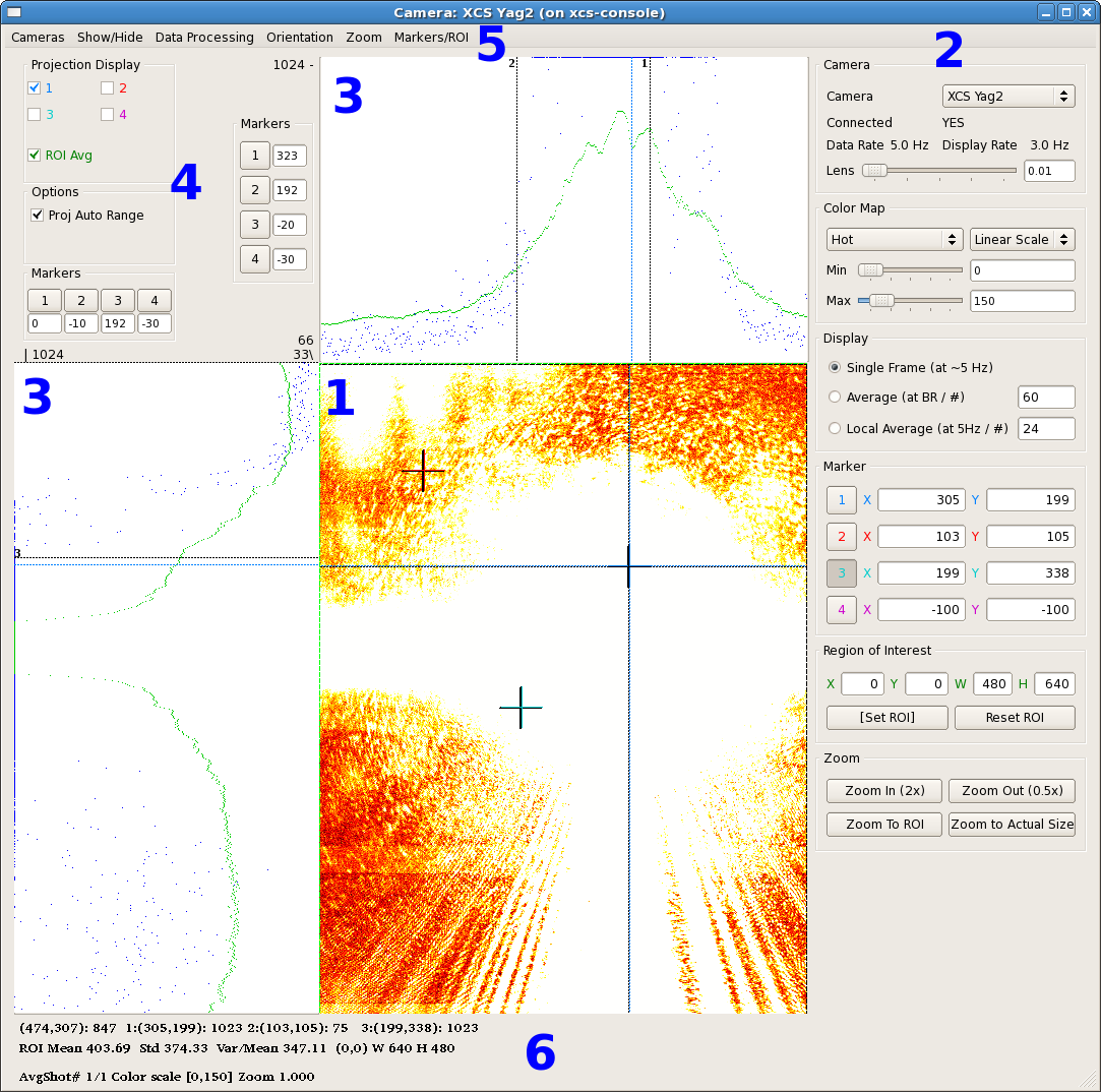
GUI Elements
1. Image
The main camera image is displayed in an area in the center of the GUI. By default, this area is 640x640 pixels, but this can be customized on the Expert Mode screen. In this image, the area has been customized to the size of the camera, 480x640. There are also three markers visible in this image, one of them being used for projections.
2. Control Panel
The control panel is shown at the right of the window. It can be hidden by unchecking the "Show Configuration" item in the "Show/Hide" menu. The controls in this area of the screen include:
- A dropdown list of cameras to select from.
- The lens control, if this camera has a lens PV.
- The colormap control. The user can select one of five colormaps: HSV, Hot, Jet, Cool, or Gray. Each of these can be set up to be linear, log, or exponential, with user-specified minimum and maximum values.
- Averaging control. The viewer can either display single frames, an on-IOC calculated average (if the IOC supports this), or a locally performed average.
- IOC image control (for camera type "IC" only, not displayed here). If the IOC supports an on-IOC region of interest selection, controls to set the region and the bit-shift are displayed here.
- On-image markers. The current location of the on-image markers are given here. The buttons to the left of these location can be enabled so that left-clicking on the image will set the marker.
Region of interest control. A region of interest can be selected in the viewer by either entering parameters or clicking on the "[Set ROI]" button and then left-clicking and dragging on the image. Clicking on the "Reset ROI" button will set the region of interest to the entire image.
- Zoom control. Controls are provided to zoom in, zoom out, zoom to the region of interest, or zoom to the actual image size.
3. Projections
Above and to the left of the main image are the projection areas. The projection can either be an average over the ROI (shown in green), or a projection in the location of an on-image marker. In the image above, both the ROI average and Marker 1 are enabled in the projection area.
A separate set of four markers is also provided in each projection window.
4. Projection Control
The projection controls are located in the upper-left corner of the window. These include:
- The projection display control, which allows selection of any or all of the on-screen markers and the ROI average to be displayed in the projection areas.
- The projection range control. If checked, this will automatically scale the projections between the minimum and maximum values. If unchecked, a constant scale from a minimum of 0 to a maximum of 1023 will be used.
- The on-projection marker control. These display the current location of the four on-projection markers. Clicking on one of the numbered buttons will allow the marker position to be set by clicking on the projection area.
5. Menus
The menus provide an alternate way of performing many of the control panel functions as well as a few other rarely-performed operations.
- Cameras
- This is a selectable list of the cameras that can be displayed.
- Show/Hide
- Configuration - If selected, show the control panel, otherwise hide it.
- Projection - If selected, show the projection areas and projection control panel, otherwise hide them.
- Expert Mode - If selected show the Expert Mode window:
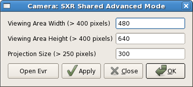
This window allows setting the main window display size as well as the dimension of the projection areas. The buttons are:
1. Open Evr - This will open the standard EVR configuration screen.
2. Apply - This will change the size of the main display screen and projection areas, if the given values are acceptably large.
3. Close - This will close the Advanced Mode window.
4. OK- This will change the size of the main display screen and projection areas, if the given values are acceptable, and close the window.
- Data Processing
- Save to File - Save the current image into a file. The type is determined by the file extension: jpg, png, bmp, pgm, and tif are supported.
- Post to E-Log - Make a post to the current experiment log that includes the current image.
- Orientation - These menu items allow the orientation to be set to either "Portrait" or "Landscape". The coordinates of the markers will be updated to match the new orientation, as will the size of the viewing area.
- Zoom - These menu items duplicate the functionality of the zoom buttons on the control panel.
- Markers/ROI
6. Information Area
Overview
Content Tools