...
| History | Date | Comments |
|---|---|---|
| 2400011 | Oct/22-Feb/23 | Resistor R108 removed Oct/2022 to debug FELIX FEC12 mode problem. R108 back on Feb/2023. |
| 2400006,2400011 | May/2/2023 | bpol2V5 mezzanine R10 330KOhm→316KOhm to raise V1.2 to V1.24 to stablelize lpGBT3,4. Overall current 0.92->1.03A. |
| 2400006/4400069 | Nov/20/2023 | Brought in V4 board 4400069 in exchange of 2400006 to go back to Bern. |
...
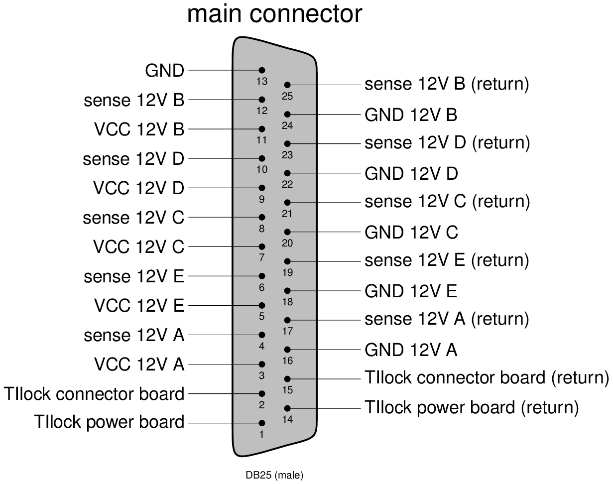
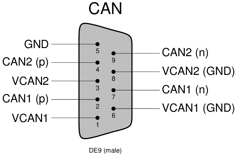
Optobox/Board service connections:
Optobox LV/DCS services:
Check the above interfaces document for more detailled description.
...
Cooling and dry air inlet/outlet: FESTO 8 mm
...
Currently no MOPS is mounted on the Powerboard inside the test-Optopanel (due to availability). We will ship one as soon as we got our hands on the Powerboard inside the test-Optopanel (due to availability). We will ship one as soon as we got our hands on them.them.
OptoBoard LV/DCS:
For optoboard standalone test setups, a mini LV/DCS service cable bundle is needed to supply 2.5V to optoboard and lead out its NTC monitoring out through the Samtec SFM-104-01-L-D connector .
Standalone optoboard LV/NTC power adaptor cable spec
Optoboard-FELIX Fiber Connectivity:
Each FELIX PCIe card has two MPO24 ports, serving 12 pairs of TX+RX each. Our lab test setups typically use fiber splitter bundles to breakout the MPO24 into individual LCs and use LC patch panels to map connectivity to the optoboard VTRX+ fiber pigtail. How the FELIX MPO24 port is structured is described in the FELIX readout and Direct FELIX confluence pages. There are two ways to breakout the FELIX MPO24:
- Most setups elsewhere and our easier setups all used MPO24→2xMPO12→24xLC splitters are described in the FELIX readout and Direct FELIX confluence pages.
- Our latest setups used direct MPO24→24xLC splitter in one step. The actual component inventory is in the "Fiber + patch" tab of the of test readout component Stanford Drive GoogleSheet.
How the VTRX+ fiber pigtail lines are structured is described in the Optosystem Interface document AT2-IP-GM-0010 (Table 4) with 5 out of 12 fibers active per optoboard which can be followed from the MPO12-LC splitter fiber color coding.
SLAC Single Optoboard Test Setup
...
Note that the Optoboard VTRX+ fiber pigtail MT ferrules connection to MPO12-LC fiber splitter is a simple slip on which requires careful manual recognition of right polarity (see ITkPixV1 readout page) which can easily slip off but prevents accidental large force breaking the fiber. It is advisable to always check the link light level with flx-info podpower to verify the fiber link is healthy (>700uW). How the VTRX+ fiber pigtail lines are structured is described in the Optosystem Interface document AT2-IP-GM-0010 (Table 4) with 5 out of 12 fibers active per optoboard. How the FELIX MPO24 port is structured and fanout with MPO24->2xMPO12→LC splitters are described in the FELIX readout and Direct FELIX confluence pages.
Current firmware allows only 2 lpGBTs to be readout, such that the link alignment string is fixed to x0000000300000000 for channels 00 and 01 in unaligned state. Alignment can be checked using data from module RX 0 (L0 on miniDP-SMA) after module configuration, giving the following link alignment strings independently of which e-links are subscribed on felixcore startup (for optoboard 2400006):
...