...
The test-Optopanel houses one Optobox with 4 Optoboards. It has a twinax inlet (round) and a fibre outlet (rectangle). The Optobox is mounted on a cooling plate with two 8 mm pipes. The
A collection of photographs from the test-Optopanel and its sister at CERN SR1 can be found here. See also this Twiki here of the SR1 test-Optopanel which has similiar information (but some very different configurations).
...
Currently no MOPS is mounted on the Powerboard inside the test-Optopanel (due to availability). We will ship one as soon as we got our hands on them.
SLAC Single Optoboard Test Setup
The initial single optoboard setup used for the early SLAC tests with single chip cards is summarized in the diagram below:
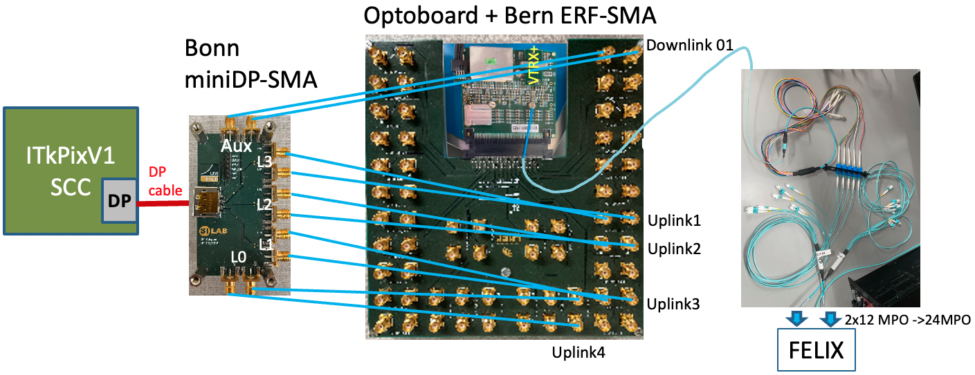
| Bonn miniDP-SMA | Bern ERF-SMA | VTRX+ fiber | FELIX fiber |
|---|---|---|---|
| AUX | DOWNLINK 01 | red (7) | TX 1 |
| LN3 | L1 UPLINK 01 | white (6) | RX 1 |
| LN2 | L1 UPLINK 02 | slate (5) | RX 2 |
| LN1 | L1 UPLINK 03 | brown (4) | RX 3 |
| LN0 | L1 UPLINK 04 | green (3) | RX 4 |
Note that the Optoboard VTRX+ fiber pigtail MT ferrules connection to MPO12-LC fiber splitter is a simple slip on which requires careful manual recognition of right polarity (see ITkPixV1 readout page) which can easily slip off but prevents accidental large force breaking the fiber. It is advisable to always check the link light level with flx-info podpower to verify the fiber link is healthy (>700uW). How the VTRX+ fiber pigtail lines are structured is described in the Optosystem Interface document AT2-IP-GM-0010 (Table 4) with 5 out of 12 fibers active per optoboard. How the FELIX MPO24 port is structured and fanout with MPO24->2xMPO12→LC splitters are described in the FELIX readout and Direct FELIX confluence pages.