Document Approval: | Date Approved |
Originator: Andy Benwell | |
Approver: Ernest Williams – Advanced Control Systems, Dept. Head | |
Approver: Carlos Serrano – LLRF Collaboration Partner | |
Approver: Larry Ruckman – HPS Common Platform System Lead | |
Approver: Matt Boyes – Deputy System Accelerator System Manager | |
Revision History
Revision | Date Released | Description of Change |
R0 | | Original Release. |
R1 | | Added extra MPS states, removed unnecessary figures |
...
...
PurposeThe LLRF to MPS/BSA interface permits high speed communication between the LCLS2 LLRF rack system and the common platform carrier. This document defines the communication link between the LCLS2 LLRF system and the common platform carrier to communicate BSA/ MPS information. This document was written after both systems passed Final Design Review(s) (FDR). Because of this, the interface is designed in light of known limitations to the physical installation and functionality of each system.
Definitions...
LLRF
...
Low Level Radio Frequency
...
SRF
...
Superconducting Radio Frequency
...
BSA
...
Beam Synchronous Acquisition
...
MPS
...
Machine Protection System
...
HPS
...
High Performance System
...
CM
...
Cryomodule
...
RFS
...
RF Station chassis
...
PRC
...
Precision Receiver Chassis
...
RES
...
Resonance control chassis
...
AMC
...
Advanced Mezzanine Card
...
I & Q
...
data
...
ATCA
...
Advanced Telecommunications Computing Architecture – the common platform architecture used at SLAC. The system is typically housed in a crate often referred to as an ATCA Crate
...
SEL
...
Self Excited Loop - LLRF regulation mode without phase or amplitude regulation. SEL is characterized by the LLRF system tracking the dynamic natural frequency of the SRF cavity
...
SELAP
...
SEL with Amplitude and Phase regulation – LLRF regulation mode with full phase and amplitude regulation. SELAP is the normal RF operating mode while the accelerator is accelerating beam.
...
Clip
...
SRF events characterized by sufficient cavity detuning that the RF system runs out of reactive power to maintain both phase and amplitude. During clip events, LLRF will briefly switch from SELAP to SEL resulting in temporary phase excursions
ScopeThe LCLS2 LLRF system is responsible regulating the RF field in SRF cavities. The LLRF system interprets RF generated faults and acts accordingly within the scope of the system, e,g, turns of RF when quench is detected. The LLRF system is responsible for sending high speed RF phase and amplitude measurements of the accelerating cavities with time stamping to the BSA system for correlation with observed beam based measurements. The LLRF system also communicates appropriate fault status or clip status to the MPS system for possible mitigation or escalation.
The LCLS2 BSA system is responsible for aggregating and storing a variety of realtime accelerator parameters from various systems. The BSA system is built upon the SLAC common carrier platform which is distributed throughout the LCLS2 accelerator. The BSA is responsible for interpreting high speed phase and amplitude values communicated from the LLRF system.
The SLAC MPS system interprets various machine status indicators including LLRF fault or clip status. The MPS system may generate higher level fault responses as appropriate from LLRF fault status. The MPS system is built upon the SLAC common carrier platform which is distributed throughout the LCLS2 accelerator.
This document defines this physical interface between the LLRF and BSA/MPS systems and defines the data structure of values passed from LLRF to BSA/MPS. This document also maps the structure of BSA data to the common platform diagnostic bus.
ReferencesAssociated Document(s) Reference Number | Document Title |
LCLSII-4.1-ES-0569-R0 | Low Level Radio Frequency ESD |
LCLSII-2.7-FR-0371-R2 | Performance and Functional Requirements for the LCLS-II Low Level RF System |
LCLSII-2.7-IC-0277-R0 | Low Level Radio Frequency (LLRF) to Accelerator Systems, Cryogenic Systems, Photon Systems, Infrastructure Systems, and LCLS-I |
LCLSII-2.7-ES-0536-R1 | HPS Common Platform Engineering Specification |
LCLSII-2.7-FR-0621-R0 | High Performance System Common Platform Functional Requirements Specifications |
Data structure, repetition rate, and resolution
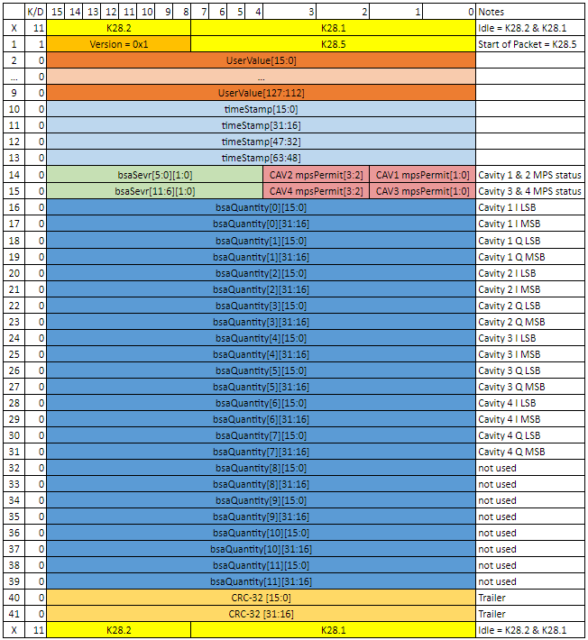
BSA and MPS data are passed from the LCLS2 LLRF system to the LCLS2 Common Platform by fiber link. The SRF cavity I&Q are calculated within the LLRF PRC chassis for 4 cavities. The severity of the BSA quantities is determined and assigned within the PRC indicating if the the data is "good" The I&Q data properly represents the state of the cavity field (SEVR = 1,1) The I&Q data does not properly represent the state of the cavity field, e.g. PLL loss of lock (SEVR= 0,0). The LLRF MPS status for the 4 cavities is also collated within the PRC. These data are packaged, with a global time stamp, and passed over the fiber link at a repetition rate of 1 MHz. The structure for data generated by 1 PRC is shown in Figure 1.
Within the structure from 1 PRC, there are 12 BSA Severity tags each with 2 bits. The severity flag will indicate if the associated cavity BSA quantity is "good" and should be evaluated as such. At this time, the LCLS2 LLRF system developers have not determined a case where data should be considered invalid. The severity for each 32 bit quantity is expected to contain two bits = 1 for valid data.
Within the structure from 1 PRC there are 12 BSA Quantities. Currently 8 of 12 quantities are defined. The BSA Quantity descriptions are shown in Figure 1, along with the associated severity for each quantity.
| Anchor |
|---|
_heading | h.3dy6vkmFigure 1: BSA / MPS datastream sctucture Within the structure from 1 PRC, there are 2 groups of 4 MPS status bits, and 12 BSA Quantities 32 bits long. Each SRF cavity corresponds to two MPS bits which allow for 4 states per cavity as described in figure 2
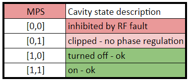
Figure 122: MPS states for LLRF cavities
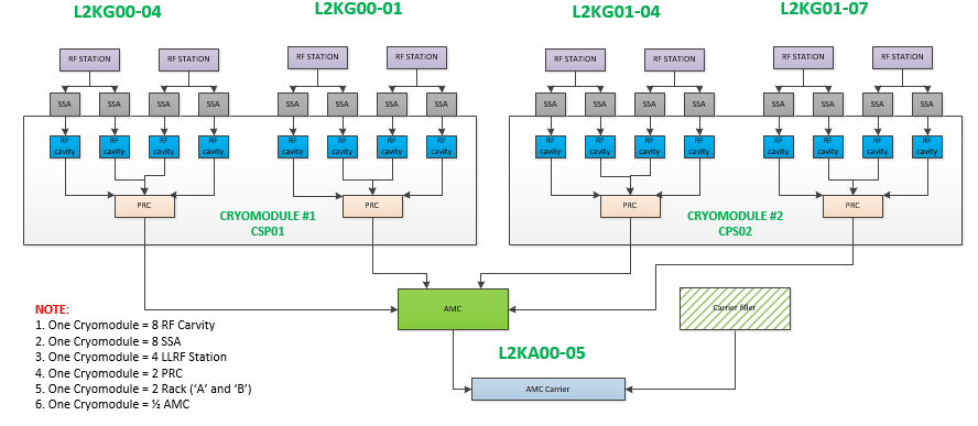
Each LLRF rack passes BSA and MPS data for 4 cavities over a single fiber connecting the LLRF PRC chassis to an AMC . As built, four PRCs are connect to each AMC through four separate fiberoptic cables. Each AMC fits with an AMC Carrier slot, such that each AMC Carrier contains 1 AMC Card and 1 AMC filler card. As a result, each AMC Carrier is processing MPS and BSA data for 4 PRCs, a total of 16 SRF cavities.
An example of the LLRF to AMC Carrier installation for LCLS2 is provided in Figure 3. For every cryomodule, there are 4 LLRF PRCs connected to 1 AMC. There is 1 AMC Carrier to process MPS/BSA data for 16 SRF cavities. The mapping demonstrates that each AMC carrier will have at least 32 quantities of 32 bit BSA data available for mapping to the LCLS2 diagnostic bus.
| Anchor |
|---|
_heading | h.1t3h5sfFigure 23: LLRF -> AMC Carrier distribution example, as built. Each AMC Carrier has 2 slots, one of which is filled by an AMC card, the other is filled by an AMC filler card (not a second AMC Card)....
Data structure, repetition rate, and resolution
The LCLS2 BSA diagnostic bus has been designed to process data at a repetition rate of 1 MHz, the full rate of the LCLS2 beam. This repetition rate is built into the AMC firmware.
The total allotment of space per AMC Carrier for BSA quantities mapped to the diagnostic bus is 24 quantities of 32 bits. This requires that the total package of 48 quantities of 32 bit data from the LLRF system be appropriately condensed to fit within the defined structure of the diagnostic bus. This is achieved by dropping the 16 Least Significant Bits (LSBs) and retaining the 16 Most Significant Bits (MSBs) in the AMC Carrier firmware.
As it is mapped to the diagnostic bus, RF BSA data is structured to fit within a standard block of 24 BSA quantities of 32 bits per 1 MHz cycle.