Page History
...
This transformation algorithm is implemented in class PSCalib.GeometryObject as discussed below.
Example of composite detector
As an example we show how composite CXI-like CSPAD detector with moving quads can be inscribed in the hierarchical geometry model and how geometry parameters can be retrieved in each level.
...
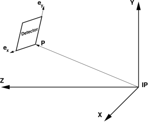 FIG. 6: Example: detector position in the experiment coordinate frame with origin at IP.
Optical
...
measurements
Precise pixel coordinates can be retrieved in a few steps using
...
Report table about all deviations is generated by the python script processing the metrology file. Large deviations exceeding standard precision >3σ(RMS) indicate on problem with measurement. A few corrections are usually applied for each metrology file.
Position of tiles in the detector
Detector pixels' geometry in 3-d can be unambiguously derived from
- the list of coordinates obtained in optical measurements,
- tile ideal geometry, and
- designed orientation of sensors in the detector.
The tile location and orientation can be defined by the table of records (see example of file: geometry/0-end.data)
| Parent name | Parent index | Object name | Object index | X0[µm] | Y0[µm] | Y0[µm] | Rotation Z [°] | Rotation Y [°] | Rotation X[°] | Tilt Z[°] | Tilt Y[°] | Tilt X[°] |
|---|
where
- Parent name - name and version of the parent object; all translation and rotation pars are defined w.r.t. parent Cartesian frame
- Parent index - index of the parent object
- Object name - name and version of the object inserted in parent frame
- Object index - index of the object
- X0, Y0, and Z0 [µm] – object frame origin coordinates in the parent frame
- Rotation X, Y, and Z [degree] – object ideal (design) rotation angle around axes Z, Y, and X of the parent frame
- Tilt X, Y, and Z [degree] – tilt angles for correction of the object rotation angles around axes Z, Y, and X of the parent frame, respectively
Tile center coordinates are defined as an average over 4 corners. Tilt angles are projected angles of the tile sides on relevant planes. Each angle is evaluated as an averaged angle for 2 sides.
Origin of the detector local frame is arbitrary. For example, for CSPAD with moving quads it is convenient to define
- 2x1 sensors' centre coordinates in the quad coordinate system as in optical measurements,
- quad origins' coordinates with respect to the point of beam crossing with the detector plane (centre of the diffraction rings), as shown on plots:
Pixel coordinates reconstruction
Pixel coordinate reconstruction in the detector frame uses
- tile ideal geometry,
- tile center positions,
- tile N·90 rotation and tilt angles.
Each geometry object pixel coordinate xj are transformed to the parent frame pixel coordinate Xi applying rotations and translations as
Xi=Rij·xj + Pi,
Calibration file
In this section we discuss requirements to the geometry alignment parameters and describe chosen file format.
Hierarchical structure
In the calibration file/table we need to save links between parent and child objects. Tree-like structure assumes that each parental object may have many children and each child object has only one parent. It is easier for each object to keep information about its parent and object location and orientation parameters with respect to the parent, as implemented in class PSCalib.GeometryObject. One fixed length record per object is convenient to keep this information in memory and file as a table. Scan over all objects allows to retrieve all hierarchical links and use them further in recursive processing. This algorithm is implemented in the class PSCalib.GeometryAccess.
Object identification
Composite detector usually consists of similar sub-detectors. In particular, CSPAD consists of four quads, quad consists of eight 2x1 sensors. Sub-detectors of the same type should be treated by the same code. To distinguish between sub-detectors we introduce two variable for each object, name and index. For example, CSPAD quads have an arbitrary symbolic name “QUAD” and indexes from 0 to 3, their children have a symbolic name “CSPAD2X1V1” and indexes from 0 to 7. The name of low level objects, “CSPAD2X1V1”, is used in the factory method PSCalib.SegGeometryStore.Create in order to instatiate associated PSCalib.SegGeometry object. This and all other names are also used to set child-parent relations between objects.
Assumptions about detector geometry
In most cases we deal with planar detectors and we assume that:
- the detector image is produced by a set of tiles,
- all tiles form almost flat (x-y) surface around z=0 within precision of production technology and installation,
- the tile rotation angles in (x-y) are N*90 degrees, where N=0,1,2,or 3, detector local coordinate system is defined
in this plane, as explained below. These assumptions are not necessary for all algorithms. But, in many cases it may be convenient to use small angle approximation or ignore angular misalignment for image mapping between tiles and 2-d image array. For this reason in calibration file we split all angles for rotation and tilt in order to have direct access to the designed and corrected values, respectively.
File format
From metrology file we may evaluate the tile center coordinates as an average over 4 corners. Tilt angles are defined as projected angles of the tile sides on relevant planes. Each angle is evaluated as an averaged angle for 2 sides. The tile location and orientation in the parent frame can be saved in the table record where

| Parent name | Parent index | Object name | Object index | X0[µm] | Y0[µm] | Y0[µm] | Rotation Z [°] | Rotation Y [°] | Rotation X[°] | Tilt Z[°] | Tilt Y[°] | Tilt X[°] |
|---|
Parent name - name and version of the parent object; all translation and rotation pars are defined w.r.t. parent Cartesian frame
- Parent index - index of the parent object
- Object name - name and version of the object inserted in the parent frame
- Object index - index of the object
- X0, Y0, and Z0 [μm] - object frame origin coordinates in the parent frame
- Rotation X, Y, and Z [degree] - object ideal (design) rotation angle around X, Y, and Z axis of the parent frame, respectively,
- Tilt X, Y, and Z [degree] - tilt angles for correction of the object rotation angles around X, Y, and Z axis of the parent frame, respectively.
First four fields are intended to set parent-to-child relations between geometry objects. Python script in CalibManager reads data from the metrology file and generates the geometry file consisting of records in this format. Thus tabulated geometry parameters allow to
- accommodate parameters from optical measurement,
- update information about sub-detectors later,
- retrieve all hierarchical links.
Result of multiple geometry transformations depends on their order. In coordinate reconstruction algorithms we use particular order for rotations and translations.
Calibration file example
CalibManager under the tabs Geometry / Metrology has a GUI which processes metrology file and generates the calibration file like shown below for CXI-like CSPAD with moving quads (see example of file: geometry/0-end.data)
| Code Block |
|---|
|
All lines started with hash “#” are comments, which are also accessible through the program interface as a dictionary. XPP-like CSPAD with all sensors attached to the same plate is measured as a single detector. Its content part omits quads
| Code Block |
|---|
|
Content of CSPAD2x2 geometry file consist of data for two sensors only:
| Code Block |
|---|
|
If the detector pixel coordinates should be presented relative to IP or other setup component, have an offset or flipped around axis one more line must to be added, for example
| Code Block |
|---|
|
or in Python code:
| Code Block |
|---|
#file: pyimgalgos/src/GeometryObject.py

def rotation(X, Y, C, S) :
    Xrot = X*C - Y*S
    Yrot = Y*C + X*S
    return Xrot, Yrot

class GeometryObject :
    ...
    def transform_geo_coord_arrays(self, X, Y, Z) :
        ...
	    # define Cx, Cy, Cz, Sx, Sy, Sz - cosines and sines of rotation + tilt angles
        ...

        X1, Y1 = rotation(X,  Y,  Cz, Sz)
        Z2, X2 = rotation(Z,  X1, Cy, Sy)
        Y3, Z3 = rotation(Y1, Z2, Cx, Sx)

        Zt = Z3 + self.z0
        Yt = Y3 + self.y0
        Xt = X2 + self.x0

return Xt, Yt, Zt |
where the 3-d rotation matrix R is a product of three 2-d rotations around appropriate axes,
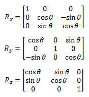
Pixel coordinates in the detector should be accessed by the method like
...
The same package and file names as in C++ but with file name extension .py:
- PSCalib/src/*.py
Summary
- *.py
Summary
Pixel detector geometry generic parameterization presented in this note is implemented in LCLS analysis software releases since ana-0.13.N. Both C++ and Python interfaces are availableSuggested method for imaging detector geometry description provides simple and unambiguous way of pixel coordinate parametrization. This method utilizes all available information from optical measurement and design of the detector and tiles. All geometry parameters are extracted without fitting technique and presented by natural intuitive way.
References
- Euler angles, Tait–Bryan angles, nautical angles, Cardan angles etc.
- Imaging Detector Geometry Implementation Notes
- Example of the file for calibration type geometry/0-end.data
...
Overview
Content Tools