Page History
...
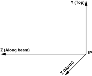
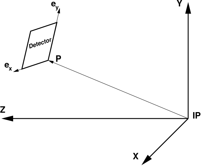

Detector coordinate system may have a translation and rotation with respect to the setup, which are defined by the 3 vectors in the setup frame:
- P – translation vector pointing from IP to the detector origin,
- ex – unit vector along the detector frame x axis,
- ey – unit vector along the detector frame y axis,
ez – is assumed to be right-hand triplet component of the vector
e=(ex, ey, ez)
Within this definition 3-d pixel coordinate "c" from in the detector frame can be easily transformed to the setup coordinate "C":
Ci=eij·cj + Pi,
where indexes "i" and "j" corresponds to the vector components in the setup and detector local coordinate frames, respectively.
Tile ideal geometry
- Assume that the detector image is produced by a set of tiles (a.k.a., segment, section, 2x1, sensor, Si-pixel matrix, etc).
- Each tile has well defined by design geometry of pixels, which does not need in separate calibration.
- Pixel (x,y) center coordinate at z=0 for each tile can be defined as a look-up table in its "natural" matrix-style coordinate system.
- For example, CSPAD 2x1 tile pixel geometry is defined as
...
Overview
Content Tools