Page History
This note describes imaging detectors' hierarchical geometry model implemented in LCLS offline software releases since ana-0.13.1.
Content
| Table of Contents |
|---|
Introduction
Note that public detector geometry data can be found here.
Nearly all imaging experiments conducted at LCLS require a precise description of the experimental geometry, especially how one or more area detectors are arranged with respect to the x-ray beam and interaction siteAnalysis of LCLS data from imaging experiments requires precise coordinate definition of the photon detection spot. In pixel array detectors photon energy is usually deposited in a single pixel and hence a description of the experimental geometry should aim to provide the pixel location to a precision should be comparable with or better than its size, for the CSPAD about 100μm. Apparently, calibration
Determination of the detector and entire experimental setup geometry with to such a precision is a challenging task for many reasons; :
- position of the detector sensors relative to interaction point (IP) of the photon beam with target is not well known,
- in some cases detector is a composition of other sub-detectors arranged together and consisting of other sub-detectors and so on for a few layers in depth,
- sub-detectors of each layer may have stable positions or be moved by stepping motor relative to each other,
- final level sub-detector is represented by precisely engineered sensor(s) of particular type(s) which geometry needs to be tabulated.
...
FIG. 1: Tentative coordinate frame of experimental setup.
In this frame photon-hit pixel coordinates (x, y, z) can be easily transformed to the photon diffraction angle θ,
...
FIG. 2: Coordinate frame of CSPAD 2x1 sensor.
Note that a right-handed rule is used for the coordinate system, so the z-axis is coming out of the page. This "native" sensor frame is initially aligned with the global coordinate system; the sensor is then positioned by applying translations and rotations relative to that native frame.
The CSPAD 2x1 tile The CSPAD 2x1 tile has
- 185 rows and 388 columns of pixels,
- regular pixel size is 109.92 × 109.92 μm²,
- pixel size in two middle columns (193 and 194) is 274.80 × 109.92 μm².
The pixel index and coordinates in the tile memory block of size 185×388 can be evaluated as
...
FIG. 3: Child object position in the parent coordinate frame.
where
- P is a translation vector pointing from parent to its child frame origin,
- ex is a unit vector along the child frame x axis,
- ey is a unit vector along the child frame y axis.
...
This transformation algorithm is implemented in class PSCalib.GeometryObject as discussed below.
Example of composite detector
...
- CSPAD 2x1 sensor (Fig. 2) is the low-level object with completely specified geometry of pixels.
- A group of eight cspad 2x1 sensors forms a quad (Fig. 4). Sensors’ positions in the quad can be measured by optical microscope.
- Four quads form a CSPAD detector. In CXI-like CSPAD quads can be moved by the stepping motor. For technical reason this detector can not be measured with optical microscope. Dedicated runs with bright images of test wires, diffraction rings, or Bragg peaks can be used to calibrate relative quad positions. Then, quads’ position variation by the stepping motor can be accounted for once calibrated quads.
- Finally, detector position relative to IP should be accounted (Fig. 6). Detector position and orientation can be measured by the ruler in the hatch for the first approximation. The same dedicated runs with bright images can be used to evaluate precise detector coordinates. Calibration runs with a few detector positions along the beam line can be helpful for full geometry parameters reconstruction.
...
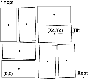
FIG. 4: Example: 2x1 sensors’ positions in the CSPAD quad coordinate frame.
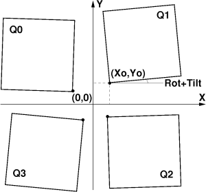
FIG. 5: Example: quads’ positions in the CSPAD detector coordinate frame.
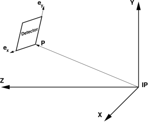
FIG. 6: Example: detector position in the experiment coordinate frame with origin at IP.
...
Optical measurements
Precise pixel coordinates can be retrieved in a few steps using
...
In the calibration file/table we need to save links between parent and child objects. Tree-like structure assumes that each parental object may have many children and each child object has only one parent. It is easier for each object to keep information about its parent and object location and orientation parameters with respect to the parent, as implemented in class PSCalib.GeometryObject. One fixed length record per object is convenient to keep this information in memory and file as a table. Scan over all objects allows to retrieve all hierarchical links and use them further in recursive processing. This algorithm is implemented in the class PSCalib.GeometryAccess.
Object identification
Composite detector usually consists of similar sub-detectors. In particular, CSPAD consists of four quads, quad consists of eight 2x1 sensors. Sub-detectors of the same type should be treated by the same code. To distinguish between sub-detectors we introduce two variable for each object, name and index. For example, CSPAD quads have an arbitrary symbolic name “QUAD” and indexes from 0 to 3, their children have a symbolic name “CSPAD2X1V1” and indexes from 0 to 7. The name of low level objects, “CSPAD2X1V1”, is used in the factory method PSCalib.SegGeometryStore.Create in order to instantiate associated PSCalib.SegGeometry object. This and all other names are also used to set child-parent relations between objects.
...
Result of multiple geometry transformations depends on their order. In coordinate reconstruction algorithms we use particular order for rotations and translations.
Calibration file example
CalibManager under the tabs Geometry / Metrology has a GUI which processes metrology file and generates the calibration file like shown below for CXI-like CSPAD with moving quads
...
| Code Block |
|---|
# HDR PARENT IND OBJECT IND X0[um] Y0[um] Z0[um] ROT-Z ROT-Y ROT-X TILT-Z TILT-Y TILT-X SETUP-IP 0 CSPAD2X2:V1 0 -100 200 1000000 0 180 0 0 0 0 |
...
Interface implementation
Program interface to the detector geometry parameters consists of a few modules with the same names up to extensions for C++ and Python in the PSCalib package. Sensor geometry:
...
C++ program interface description with examples is available in Doxygen documentation. Below we consider Python interface only.
Access to sensor geometry information
...
| Code Block |
|---|
from PSCalib.SegGeometryCspad2x1V1 import cspad2x1_one ... xarr, yarr, zarr = cspad2x1_one.pixel_coord_array() |
or using generic access method through the factory method:
| Code Block |
|---|
fromfrom PSCalib.SegGeometryStore import sgs ... sg = sgs.Create(’SENS2X1:V1’, pbits=0377) xarr, yarr, zarr = sg.pixel_coord_array() |
return the same x-, y-, and z-coordinate arrays of shape=[185,388].
This interface is used internally in the geometry service modules and, until it is absolutely necessary, should not be used directly. Doxygen/Sphinx documentation for C++/Python modules is available in References.
Pixel coordinates transformation
...
| Code Block |
|---|
#file: pyimgalgos/src/GeometryObject.py

def rotation(X, Y, C, S) :
    Xrot = X*C - Y*S
    Yrot = Y*C + X*S
    return Xrot, Yrot

class GeometryObject :
    ...
    def transform_geo_coord_arrays(self, X, Y, Z) :
        ...
	    # define Cx, Cy, Cz, Sx, Sy, Sz - cosines and sines of rotation + tilt angles
        ...
        X1, Y1 = rotation(X,  Y,  Cz, Sz)
        Z2, X2 = rotation(Z,  X1, Cy, Sy)
        Y3, Z3 = rotation(Y1, Z2, Cx, Sx)

        Zt = Z3 + self.z0
        Yt = Y3 + self.y0
        Xt = X2 + self.x0

return Xt, Yt, Zt |
Detector geometry access interface
...
| Code Block |
|---|
from PSCalib.GeometryAccess import *
fname_geometry = ’<path>/geometry/0-end.data’
geometry = GeometryAccess(fname_geometry, 0377)

pix_size = geometry.get_pixel_scale_size()
X, Y, Z = geometry.get_pixel_coords(’QUAD:V1’, 1) # for quad
X, Y, Z = geometry.get_pixel_coords() # for top object (CSPAD)
iX, iY = geometry.get_pixel_coord_indexes(’QUAD:V1’, 1, pix_scale_size_um=None, xy0_off_pix=None) # for quad
iX, iY = geometry.get_pixel_coord_indexes(xy0_off_pix=(1000, 1000)) # for top object (CSPAD)
img = img_from_pixel_arrays(iX,iY,W=<intensity-array>)
img = img_from_pixel_arrays(iX,iY) # Image of 0/1 for fake/real pixels
arr = geometry.get_pixel_mask(’QUAD:V1’, 1, 1+2+4+8)
arr.shape = (8,185,388)

dict_comm = geometry.get_dict_of_comments()
d = geometry.get_dict_of_comments()
print "d[’DATE_TIME’] = %s" % d[’DATE_TIME’]
|
Summary
Geometry File Format Conversion
crystfel/cheetah/psana
Mikhail Dubrovin has created geometry-conversion scripts. Documentation can be found here: Geometry converter between psana and CrystFEL.
TJ Lane has created geometry-conversion scripts. These were originally in github (https://github.com/LinacCoherentLightSource/psgeom) but have been moved into psana. The methods can be accessed in python but an easier to use wrapper script called "geoconv" has been created. Use "geoconv --help" to see the current syntax.
cctbx/psana
Cctbx.xfel conversion instruction can be found here: http://viper.lbl.gov/cctbx.xfel/index.php/Cxi02416_calibration. Use the following command to convert cbf to psana format:
cxi.cbfheader2slaccalibThere's a command to go from psana format to cctbx, it's not documented above but Aaron Brewster says it is
cxi.slaccalib2cbfheader
Summary
Pixel detector geometry generic parameterization presented in this note is implemented in LCLS analysis software releases since ana-0.13.N. Both C++ and Python interfaces are available.
| Anchor | ||||
|---|---|---|---|---|
|
...
- geometry.pdf - this note in PDF format
- Euler angles, Tait–Bryan angles, nautical angles, Cardan angles etc.
- Autogenerated docs - API description for C++ and Python code
- Python API:
- PSCalib.SegGeometry - abstract interface for sensor pixels geometry description.
- PSCalib.SegGeometryCspad2x1V1 - implementation of interface for CSPAD 2x1 sensor of version V1.
- PSCalib.SegGeometryStore - static factory method for all available sensor geometry descriptors.
- PSCalib.GeometryObject - class to support one object/node in hierarchical structure.
- PSCalib.GeometryAccess - class to support hierarchical structure and access to the geometry parameters.
- LAMP_User_Manual.
...
- pdf (useful for determining geometry orientation associated with pnCCD readout order (see table 3))
- Detector alignment tool
- Calibration Management Tool
Overview
Content Tools