Page History
| Include Page | ||||
|---|---|---|---|---|
|
| Table of Contents |
|---|
2x1 Sensor Geometry
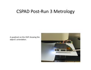
Optical measurement
Optical measurement is maintained by Chris Kenney. Detector or its quad is installed on microscope table and 3-d coordinates of all 2x1 sensor corners are measured with precision about 8um (RMS) in x-y plane. All corners in the measurement are numerated in arbitrary order. It is expected that numeration order should be the same for different measurements. This procedure depends on CSPAD construction;
- For CSPAD with moving quads (i.e. for CXI) optical measurement is done separately for each quad. The numeration of corners is shown in the plot:
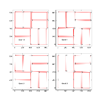
The same plots in PDF format: CSPAD quad metrologyCXI pixel layout
For each quad measurement is started from the point #1 which in assembled detector is closest to the beam. The 1-st point (x,y,z) coordinates are re-set to (0,0,0) in the beginning of measurements. At the end, it is checked that the 1-st point coordinates are reproduced within precision of measurement.
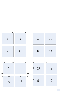
- For CSPAD with fixed quad geometry (i.e. for XPP) optical measurement is done for entire detector. The numeration of corners in this case is shown in the plot:
The 1-st corner of the 3-rd quad (x,y,z) coordinates are re-set to (0,0,0) in the beginning of measurements. At the end, it is checked that the 1-st point coordinates are reproduced within precision of measurement.
Corner coordinates are measured in micrometers (um) and are saved in the xlsx format table, also containing numeration of quads and points. Then, xlsx format table is converted to the text format in order to feed the python script for quality check and getting calibration parameters for 2x1 center coordinates and tilt angles.
Example of tables for CXI:
Example of tables for XPP:
QC procedure
For quality chech we calculate
S1 - 1st short side length of 2x1
S2 - 2nd short side length of 2x1
L1 - 1st long side length of 2x1
L2 - 2nd long side length of 2x1
D1 - 1st diagonal of 2x1 between corners 1 and 3
D2 - 2nd diagonal of 2x1 between corners 2 and 4
dS and dL are the deviations of the 1st and 2nd corner along the short and long sides, respectively. The sign of all dS are chosen in order to provide correct sign for the tilt angle (the same direction for all 2x1 sensors).
<dS/L> - the tilt angle of 2x1 averaged over two sides in radians.
angle(deg) - the same angle in degrees.
dD = D1 - D2
d(dS) = dS1 - dS2
d(dL) = dL1 - dL2
Quality check parameters for the perfect measurement:
S1=S2, L1=L2 - the 2x1 sides should have equal length and width,
D1=D2 - the 2x1 diagonals should be equal,
dS1 = dS2 = 2*dL1 =2*dL2 - tilt angle should provide consistent deviation for all corners,
dD=0, d(dS)=0, and d(dL)=0 - within precision of measurement.
Everything, excluding <dS/L> and angle(deg), are in micrometers.
Example of the table:
| Include Page | ||||
|---|---|---|---|---|
|
Introduction
Cornell SLAC Pixel Array Detector (CSPAD) is an imaging X-ray detector made of silicon sensors (2x1) covering about 20x20cm² surface, as shown in the plot:
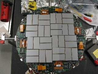
Pixel coordinates in 2x1 sensor chip are known with sub-micrometer precision. Construction of the detector allows significant freedom in relative positions of 2x1 sensors. To get precise pixel positions in the detector the 2x1 sensor coordinates needs to be calibrated. In this note we describe geometry of the CSPAD detector, optical and quad alignment procedure, parameters, and software providing access to precise geometry information.
2x1 Sensor Geometry
The 2x1 sensor geometry was tested with microscopic measurement. Two slides from Chris Kenney's presentation shows the pixel sizes:
![]()
![]()
The same slides in PDF format.
Important 2x1 features:
- Number of rows x columns = 185 x 388. (In DAQ notation of rows and columns is interchanged...)
- Most of pixels have size 109.92 x 109.92 um².
- Gap between two ASICS is covered by the two rows of elongated pixels with size 109.92 x 274.8 um².
- Two versions of sensors have different dimensions between corners, so it is reasonable to define pixel coordinates w.r.t. the sensor center.
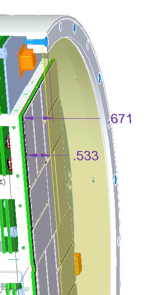
Shield to sensor distance
Chart of CXI Camera1 provided by Serge Guillet on 2017-06-12.
Optical measurement
Optical measurement is conducted by Gabriel Blaj. Detector or its quad is installed on microscope table and 3-d coordinates of all 2x1 sensor corners are measured with precision about 8um (RMS) in x-y plane. All corners in the measurement are numerated in arbitrary order. It is expected that numeration order should be the same for different measurements. This procedure depends on CSPAD construction;
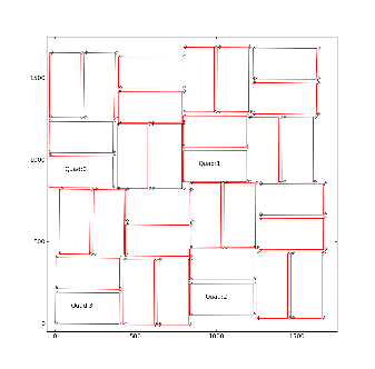
- For CSPAD with movable quads (i.e. for CXI) optical measurement is done separately for each quad. The numeration of corners is shown in the plot:
The same plots in PDF format: CSPAD quad metrology and CSPAD pixel layout in quads.
For each quad measurement is started from the point #1 which in assembled detector is closest to the beam. The 1-st point (x,y,z) coordinates are re-set to (0,0,0) in the beginning of measurements. At the end, it is checked that the 1-st point coordinates are reproduced within precision of measurement.
| Note |
|---|
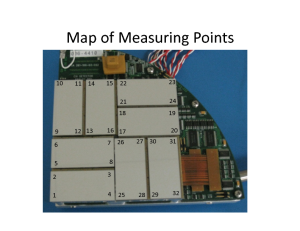
The order of points in optical measurement does not coincide with numeration of 2x1 in DAQ, as shown in the plot (and in PDF file): |
- For CSPAD with fixed quad geometry (i.e. for XPP) optical measurement is done for entire detector. The numeration of corners in this case is shown in the file XPPMetrologyAnnotated.pdf and in the plot:
The 1-st corner of the 3-rd quad (x,y,z) coordinates are re-set to (0,0,0) in the beginning of measurements. At the end, it is checked that the 1-st point coordinates are reproduced within precision of measurement.
Corner coordinates are measured in micrometers (um) and are saved in the xlsx format table, also containing numeration of quads and points. Then, xlsx format table is converted to the text file format in order to use it in python script.
Example of tables for CXI:
Example of tables for XPP:
- Metrology in XLSX
- Metrology in TXT Python script converts this table to the table with standard numeration of points in quads:
- Metrology in standard TXT
Then, text table with "standard" numeration of points in quads is feed to the python script which provides quality check of optical measurement and evaluates the alignment parameters for quads. In the beginning, this script changes the numeration of points adopted in optical measurement to numeration of 2x1 used in DAQ. Further, all calibration parameters are associated with numeration of 2x1 sensors and quads in DAQ.
Quality Check Procedure
For quality check of optical measurement we calculate
S1 - 1st short side length of 2x1
S2 - 2nd short side length of 2x1
L1 - 1st long side length of 2x1
L2 - 2nd long side length of 2x1
D1 - 1st diagonal of 2x1 between corners 1 and 3
D2 - 2nd diagonal of 2x1 between corners 2 and 4
dS and dL are the deviations of the 1st and 2nd corner along the short and long sides, respectively. The sign of all dS are chosen in order to provide correct sign for the tilt angle (the same direction for all 2x1 sensors).
<dS/L> - the tilt angle of 2x1 averaged over two sides in radians.
angle(deg) - the same angle in degrees.
dD = D1 - D2
d(dS) = dS1 - dS2
d(dL) = dL1 - dL2
dz3(um) - signed distance from 2x1 sensor plane and corner 3, where the 2x1 sensor plane contains the corner points p1, p2, and p4. This plane is defined by the vectors v21=p2-p1, v41=p4-p1, and their orthogonal vector
| Code Block |
|---|
vort = [v21 x v41].
|
Scalar product with normalization defines the distance from point 3 to the 2x1 plane containing 3 other points:
| Code Block |
|---|
dz3 = (v31 * vort) / |vort|.
|
Quality check parameters expected for perfect geometry:
S1=S2, L1=L2 - the 2x1 sides should have equal length and width,
D1=D2 - the 2x1 diagonals should be equal,
dS1 = dS2 ? (388/185)*dL1 = (388/185)*dL2 - tilt angle should provide consistent deviation for all corners,
dD=0, d(dS)=0, and d(dL)=0 - within precision of measurement.
dz3(um) = 0
Everything, excluding <dS/L> and angle(deg), are in micrometers.
Example of the table with quality check results:
| Code Block |
|---|
pair:        S1      S2     dS1     dS2        L1      L2     dL1     dL2    <dS/L>  angle(deg)      D1      D2      dD   d(dS)   d(dL)    dz3(um)

Quad  0
pair: 0   20891   20913     200     222     43539   43541    -102    -100    0.00485    0.27766   48298   48297       1     -22      -2      2.981
pair: 1   20910   20894     293     277     43540   43535    -127    -132    0.00655    0.37506   48302   48289      13      16       5    -23.986
pair: 2   20890   20906      99      83     43536   43536      42      42    0.00209    0.11976   48290   48293      -3      16       0     -3.034
pair: 3 20897 20895 131 133 |
| Code Block |
pair: S1 S2 dS1 dS2 L1 L2 dL1 dL2 <dS/L> angle(deg) D1 D2 dD d(dS) d(dL) Quad 0 pair: 0 20891 20913 200 222 43539 43541 -102 -100 0.00485 0.27766 48298 48297 1 -22 -2 pair: 1 20910 20894 293 277 43540 43535 -127 -132 0.00655 0.37506 48302 48289 13 16 5 pair: 2 20890 20906 99 83 43536 43536 42 42 0.00209 0.11976 48290 48293 -3 16 0 pair: 3 20897 20895 131 133 43545 43543 65 63 0.00303 0.17369 48299 48297 2 -2 2 pair: 4 20911 20896 -30 -45 43549 43547 17 15 -0.00086 -0.04934 48303 48306 -3 15 2 pair: 5 20901 20898 10 7 43540 43544 -8 -4 0.00020 0.01119 48296 48299 -3 3 -4 pair: 6 20904 20903 104 105 43536 43540 55 59 0.00240 0.13752 48302 48290 12 -1 -4 pair: 7 20901 20901 -7 -7 43545 43543 -365 63 -5 -0.0001600303 -0.0092117369 48299 4830148297 -2 -2 0 2 2 Quad 16.003 pair: 4 0 20911 20913 20896 20914 -34330 -34245 4354043549 43547 43550 17 165 17515 -0.0078700086 -0.4506604934 4831348303 4830348306 -3 10 15 -1 -10 2 -5.994 pair: 15 20901 20898 20901 10 -145 -1427 4354843540 43544 43551 -8 62 -4 65 -0.0033000020 -0.1888001119 4830048296 4830948299 -93 -3 -34 9.993 pair: 26 2089520904 20903 -151 104 -159 105 43536 4353543540 43532 55 -74 59 -77 -0.0035600240 -0.2040013752 48302 4828948290 48291 12 -2 -1 8 -4 352.002 pair: 37 2087220901 2090920901 -357 -727 43545 43541 43543 43554 -373 -245 -0.0012300016 -0.0703900921 4829448299 4830348301 -92 0 2 37 14.001 Quad -131 pair: 40 2094020913 2090420914 -455343 -491342 4352743540 4355443550 214165 241175 -0.0108600787 -0.6224245066 48313 4830948303 48309 10 0 -1 36 -10 -2724.002 pair: 51 2091020898 2090320901 -302145 -309142 43548 43546 43551 43546 62 145 14565 -0.0070200330 -0.4019618880 4830448300 4830748309 -39 -3 7 -3 0-23.005 pair: 62 2090120895 2091920903 -421151 -439159 4352943535 4353943532 -21374 -20377 -0.0098800356 -0.5659320400 4829648289 4829848291 -2 18 8 -10 3 -17.995 pair: 73 2090720872 2090720909 -452235 -452272 4354843341 43354 43539 -20137 -21024 -0.0103800585 -0.5947533507 4831548201 4829448036 165 21 37 0 -13 9 Quad 2 -13.010 pair: 04 2091420940 20914 20904 -25 455 -25491 4353643527 4354043554 214 10 14241 -0.0005701086 -0.0329062242 4830048309 4830048309 0 36 0 -4 pair: 1-27 20901 208971.101 pair: 5 20910 20903 7 -302 3-309 43546 4353643546 145 -1 145 -11 -0.0001100702 -0.0065840196 4829348304 4830048307 -73 7 4 100 6.016 pair: 26 2089920901 2090320919 -256421 -260439 4353343529 43539 -127213 -121203 -0.0059300988 -0.3395456593 4829348296 4829448298 -12 18 4 -10 -68.026 pair: 37 2091220907 2090420907 -210452 -202452 4354043548 4354743539 -106 201 -99210 -0.0047301038 -0.2710659475 48315 48294 48300 4830621 -6 0 -8 9 -7 -8.982 Quad 2 pair: 0 4 20914 20910 20914 20903 -54325 -55025 43536 43535 43540 43536 10 261 26214 -0.0125500057 -0.7192303290 4829848300 4829948300 -10 70 -1 pair:4 5 20904 -11.013 pair: 1 20905 20901 -24120897 -240 7 43538 43544 3 111 43546 11743536 -0.00552 -0.316471 48298 -11 48301 0.00011 -30.00658 48293 -148300 -6 pair:7 6 20903 209024 2110 22 4.036 pair: 2 20899 43539 20903 43543 -256 8-260 43533 12 43539 0.00049 -127 0.02829 -121 48298 -0.00593 48298 -0.33954 48293 048294 -1 -4 pair: 7 20902 -6 20903 -1.023 pair: 3 82 20912 20904 81 -210 43546 -202 43547 43540 35 43547 -106 36 -99 -0.0018700473 -0.1072327106 48300 48306 -6 -8 1 -7 -1 Quad 324.004 pair: 04 2090220910 20898 20903 -82543 -86550 4353643535 4354343536 261 30 262 37 -0.0019301255 -0.1105471923 48298 48289 48299 48302 -131 47 -7 pair: 1 20900 20904 0.004 pair: 5 20904 20905 79 -241 83 -240 43548 43538 43541 43544 -35 111 -42 117 -0.0018600552 -0.1065831647 48298 48301 48301 -3 0 -1 -4 -6 7-6.024 pair: 26 2091220903 2089420902 181 21 199 22 43536 43539 43535 43543 97 8 96 12 0.0043600049 0.2500502829 48298 48298 48289 0 9 -18 1 -4 18.999 pair: 7 3 20902 20912 20903 20905 82 119 12681 4353943546 4353843547 5735 5636 0.0028100187 0.1612110723 4829648300 4830148306 -56 -7 1 -1 pair: 4 20894 209129.995 Quad 3 pair: 0 20902 20898 -45482 -43686 43536 43534 43543 43545 30 212 22337 -0.0102200193 -0.5856011054 48289 48302 48303 -13 48296 4 7 -187 -111.994 pair: 51 2090620900 2091920904 -336 79 -323 83 43527 4353543548 43541 155 -35 163 -42 0.0075700186 -0.4336910658 4829548301 4829448301 0 1 -134 7 -817.993 pair: 62 2090220912 2090520894 -203 181 -206 199 43537 43536 43525 43535 -89 97 -101 -0.00470 96 -0.26916 482930.00436 0.25005 48298 48289 48287 9 6 -18 3 1 1210.011 pair: 3 7 20912 20900 20905 20897 119 -140 -137126 43539 4354443538 -68 57 -63 56 -0.00318 -0.1822500281 482980.16121 48296 48301 2 -5 -3 -7 1 -5 |
This quality check works well to catch significant typos in input table. In case of obvious typos input table can be corrected. When the quality check is passed successfully the alignment parameters are saved in deployed under the calib directory as explained below.
Alignment parameters
The official place for CSPad alignment parameters is
/reg/d/psdm/<INSTRUMENT>/<experiment>/calib/CsPad::Calib<VERSION>/<CSPad-name>/<type>/<run-range>.data
The file name consists of the run range followed by the .data, for example, 0-end.data, 11-end.data, 47-52.data, etc.
Description of types
All CSPAD geometry alignment parameters are split for 9 types:
center- x, y, z center position of each 2x1 for all quadrants. Comes from optical measurement.center_corr- additional manual correction to the center parameter. Can be applied if the optical measurement has (non-)obvious problems.marg_gap_shift- margins, gaps, and shifts between quads, as explained below. Comes from image-based tuning.offset- x, y, z coordinates for 4 quads. Fairly-reasonable assigned before tuning of theoffset_corrandmarg_gap_shiftparameters.offset_corr- additional correction to the offset. Comes from image-based tuning.quad_rotation- 4 quad rotation in n*90 degree. Comes from basic geometry.quad_tilt- 4 quad tilt in fractional degree. Has never been used. In latest optical measurement is accounted through the global 2x1 coordinate measurement in the detector.rotation- 8 2x1-rotation angle for 4 quads in n*90 degree. Comes from basic geometry.tilt- 8 2x1-tilt angle for 4 quads in fractional degree. Comes from optical measurement.
All coordinates are defined in size of pixel, which is 109.92 x 109.92um (and 274.80 x 109.92um for two rows between two of 2x1 ASICs.) The quadrant size is pre-defined as 850x850. The margins, shifts and gaps are defined for these quads. The offset and offset_corr are defined for low-left angle of the rotated by n*90 degree quad. Size of entire CSPad image does not matter for this alignment.
center
The tail of the path: center/<run-range>.data
...
center_corr
The tail of the path: center_corr/<run-range>.data
...
offset
The tail of the path: offset/<run-range>.data
...
offset_corr
The tail of the path: offset_corr/<run-range>.data
...
offset_corr
The tail of the path: offset_corr/<run-range>.data
| Code Block |
|---|
dXq0 dXq1 dXq2 dXq3
dYq0 dYq1 dYq2 dYq3
dZq0 dZq1 dZq2 dZq3
|
marg_gap_shift
The tail of the path: marg_gap_shift/<run-range>.data
| Code Block |
|---|
        offset of 2x1s in quad (for tilt)
       /  offset of quads in image (for tilt)
      /  /  gaps
     /  /  /  shifts
    /  /  /  /
X: 15 40 0 32
Y: 15 40 0 32
Z: 0 0 0 0
|
quad_rotation
The tail of the path: quad_rotation/<run-range>.data
...
quad_tilt
The tail of the path: quad_tilt/<run-range>.data
...
rotation
The tail of the path: rotation/<run-range>.data
...
tilt
The tail of the path: tilt/<run-range>.data
...
References
16.000
pair: 4   20894   20912    -454    -436     43534   43545     212     223   -0.01022   -0.58560   48303   48296       7     -18     -11      2.023
pair: 5   20906   20919    -336    -323     43527   43535     155     163   -0.00757   -0.43369   48295   48294       1     -13      -8      5.993
pair: 6   20902   20905    -203    -206     43537   43525     -89    -101   -0.00470   -0.26916   48293   48287       6       3      12      2.981
pair: 7   20900   20897    -140    -137     43539   43544     -68     -63   -0.00318   -0.18225   48298   48296       2      -3      -5     29.997
|
This quality check works well to catch significant typos in input table. In case of obvious typos input table can be corrected. When the quality check is passed successfully the alignment parameters are saved and deployed under the calib.
Detector geometry model
Since 2014 we support universal detector geometry software which is documented in the Detector Geometry page and in CSPAD-geometry-parameters.pdf.
Alignment parameters from optical measurement
From optical measurement we extract coordinates of the center of each 2x1 sensor and its tilt angle.
The center coordinates are evaluated as an averaged over 4 corners measurements for each axis.
The tilt parameters are used along with rotation to completely define orientation of 2x1 in quad (for CXI) or in detector (for XPP).
Alignment of quads in the detector
For CSPad with fixed quad geometry (like in XPP) optical measurement of entire detector (should) produces complete information for geometry alignment.
For CSPad with moveable quads (like in CXI) quads relative position needs to be adjusted through the alignment parameters for quads. It is usually done using typical images with diffraction rings, wires or other shading objects:
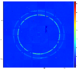
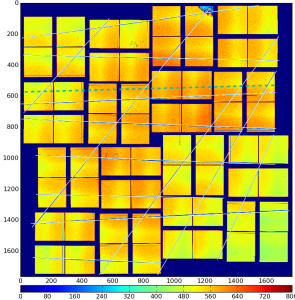
Although few algorithms of automatic quad alignment were tried, we did not find good generic way for automated quad tuning. Currently, the quad tuning parameters in marg_gap_shift and offset_corr are adjusted manually for runs with specific images.
Calibration store
The official space for CSPAD alignment parameters is
/reg/d/psdm/<INSTRUMENT>/<experiment>/calib/CsPad::Calib<VERSION>/<CSPad-name>/<type>/<run-range>.data
For example:
| Code Block |
|---|
/reg/d/psdm/CXI/cxi80410/calib/CsPad::CalibV1/CxiDs1.0:Cspad.0/geometry/1142-end.data
|
The file name consists of the run range followed by the .data extension, for example, 0-end.data, 11-end.data, 47-52.data, etc.
Calibration type
Detector geometry calibration information is located in a single file of type
geometry- contains hierarchical description of all detector components; for example for CSPAD, sensors' location and rotation in the quads, quads - in the detector, detector - in the setup, etc.
Archive and History
Optical measurement and other alignment files can be found in
- /reg/g/psdm/detector/alignment/cspad/
- Geometry History
Detector data access software
References
- CSPAD Geometry and Alignment - Depricated - old version of this page
- Detector Geometry - confluence page
- CSPAD in DAQ - schematic description of CSPAD geometry available in DAQ.
- CSPAD quad metrology - slides for CXI type CSPAD quads
- CSPad pixel layout in quads - pdf file with numeration of ASICs in the CSPAD quads
- XPPMetrologyAnnotated.pdf - order of measurements of XPP camera.
- Geometry History - page with references to calibration files.
- Detector data access software - auto-generated documentation of the Detector package.
...
Overview
Content Tools