Page History
| Table of Contents |
|---|
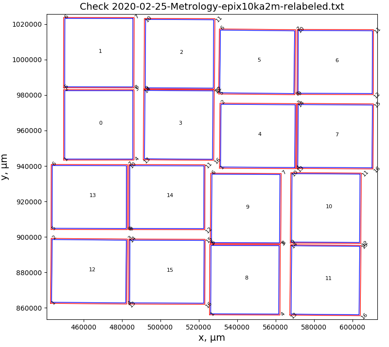
Why do I think that 2020-02-25 optical metrology is good
- metrology was done on 2020-02-25 for new detector which currently labeled on connectors side as ePix10k2M 1, also known as epix10ka2m.1, 2M.1 etc.
- very good quality check
- all z-measurements are around 1 feet, have a lit lot of repeatable numbers - can't be trusted
...
- red rectangles - for points measured in optical metrology
- blue rectangles - panels reconstructed from geometry file

DAQ panel indexes in optical metrology possible detector orientations
| Code Block | ||
|---|---|---|
| ||
        rot = 0  ^y
        Q0  1  3 |  4  5  Q1
            0  2 |  6  7
        ---------+----------> x
           15 14 | 10  8
        Q3 13 12 | 11  9  Q2

        rot = 1  ^y
        Q3 13 15 |  0  1  Q0
           12 14 |  2  3
        ---------+----------> x
           11 10 |  6  4
        Q2  9  8 |  7  5  Q1

        rot = 2  ^y
        Q2  9 11 | 12 13  Q3
            8 10 | 14 15
        ---------+----------> x
            7  6 |  2  0
        Q1  5  4 |  3  1  Q0

        rot = 3  ^y
        Q1  5  7 |  8  9  Q2
            4  6 | 10 11
        ---------+----------> x
            3  2 | 14 12
        Q0  1  0 | 15 13  Q3
|
Images of panels in data for all detector orientations in metrology processing v1 without quads
- v1 of the metrology processing script represents simplest approach - each panel coordinates are taken as is to insert in the detector
- data from mfxc00118 run44 silver-behenate sample


Summary:
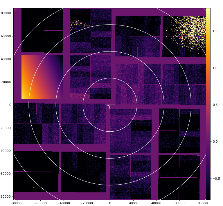
- data panel 1 (numerated from 0 to 15) is replaced by intensity ascending array, darkest corner is (0,0) pixel.
Summary:
- numeration of quads at rotation looks symmetric - so seems right
- one orientation of the detector gives correct image and it shows smallest offsets between panels in quads
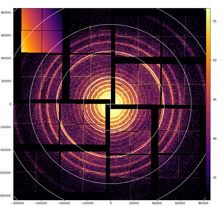
mfxc00118 run44 silver-behenate

mfxc00318 run 10,13 lysozyme
psana direct and mirror image for crystfel


Geometry files centered for mfxc00318 run13 lysozyme
...
Detector orientation in the hutch
mfxc00118 runs 70-73 for Fe55 in the corner of quad 0-3
| Code Block | ||
|---|---|---|
| ||
   ^y          |
Q0 | Q1        |
---+----->x    |
Q3 | Q2 V g (gravity) |
Panel 0 data is replaced by the ascending intensity array, (0,0) pixel is in the darkest corner.


mfxc00118 run44 silver-behenate
panel 1 is marked
mfxc00318 run 10,13 lysozyme
psana direct and mirror image for crystfel
panel 0 is marked on full size image
Geometry files centered for mfxc00318 run13 lysozyme
- 2020-02-25-geometry-epix10ka2m.1-v1-mfxc00318-0013-z0.txt
- 2020-02-25-geometry-epix10ka2m.1-v1-mfxc00318-0013-z0-mirror.txt
- 2020-02-25-geometry-epix10ka2m.1-v1-mfxc00318-0013-z0-mirror-crystfel.txt
Geoptimizer or how geometry can be screwed-up
First, thanks to Olexandr and Marina for discovering how our geometry should be mapped to data array.
| Code Block | ||||
|---|---|---|---|---|
| ||||
Yefanov, Oleksandr <oleksandr.yefanov@cfel.de> Tue 8/18/2020 1:18 PM
To: Dubrovin, Mikhail; O'Grady, Paul Christopher
Cc: Hart, Philip Adam; Chun Hong Yoon <chuckyoon@stanford.edu>; Batyuk, Alex; Mariani, Valerio; McKelvey, Mark E
2 attachments (5 MB)Download allSave all to OneDrive - SLAC National Accelerator Laboratory
Hi Michail and others,
We’ve found the problem!!!!!
Hi Michail and others,
We’ve found the problem!!!!!
Sorry to say, but it’s from your side. :)
Solution at the end of the e-mail as a bonus for those who read the whole e-mail. :)
Actually I’ve written the e-mail while searching for the answer. But the text might be useful for those who work with geometries.
I believe that the optical metrology is right – I was wrong once, by thinking that CS-PAD metrology was not good and I don’t want to repeat my mistake. :)
But as with CS-PAD I’m afraid the problem is with attributing the optical metrology to the measured data. (here I’m right – see below :)
Unfortunately your arguments about influence of z-offset or out-of-plane tilts can be discarded using simple math.
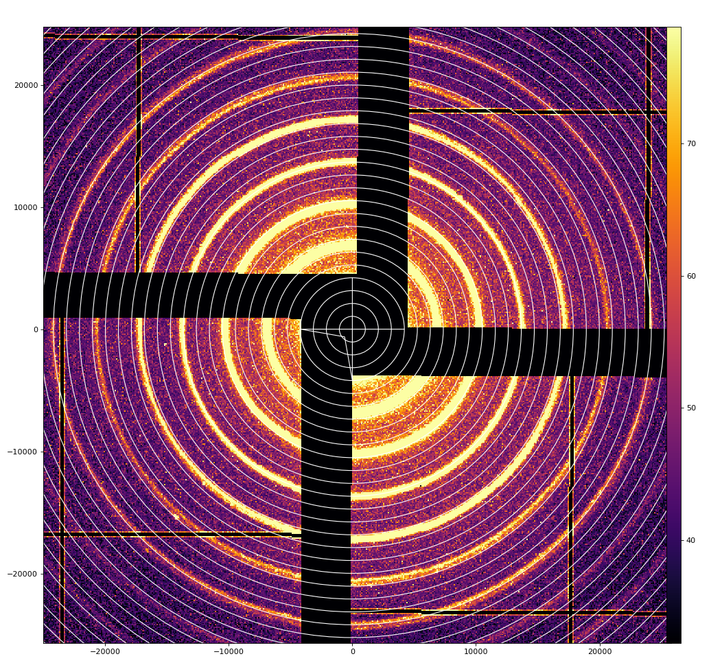
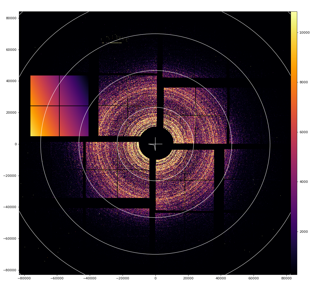
For example at the attached image (…current.png) the middle green ring has radius of 200px = 20mm and the detector is approx. at 120mm. So to have in-plane offset of 2 pixels you’d need to shift a panel by 2mm. That’s too much. Also, as you can see, at left-bottom panel the rings overlap at the top side, but have distance at the left side of the panel. So to correct it you’d need out-of-plane rotation. 2 pixels (at 200px distance) would correspond to 11.5 degrees. Not realistic. :( And in the attached example error is 4-5 pixels!!! I’m not even mentioning that in case of the tilts and z-offset the behavior is different at different parts of the panel. You can see the effect of these distortions from geoptimizer’s error map.
The interesting observation is that I really see z-offset for panels and it is quite big (up to 1mm for corner panel). Fortunately in my algorithm z-offset cannot be confused with x-y (different parameter is considered), but as I mentioned, due to the geometry of the detector z-offset is much more sensitive to noise/error (for example wrong peaks). Therefore to find reliable z-offset of different panels I need more data. I’ve made a very good geometry for AGIPD (with z-offset up to 1mm) using ONLY measured data (optical metrology doesn’t exist for AGIPD), so it is actually possible. I’ll try to optimize z later when I have access to more data.
Now SOLUTION !!!
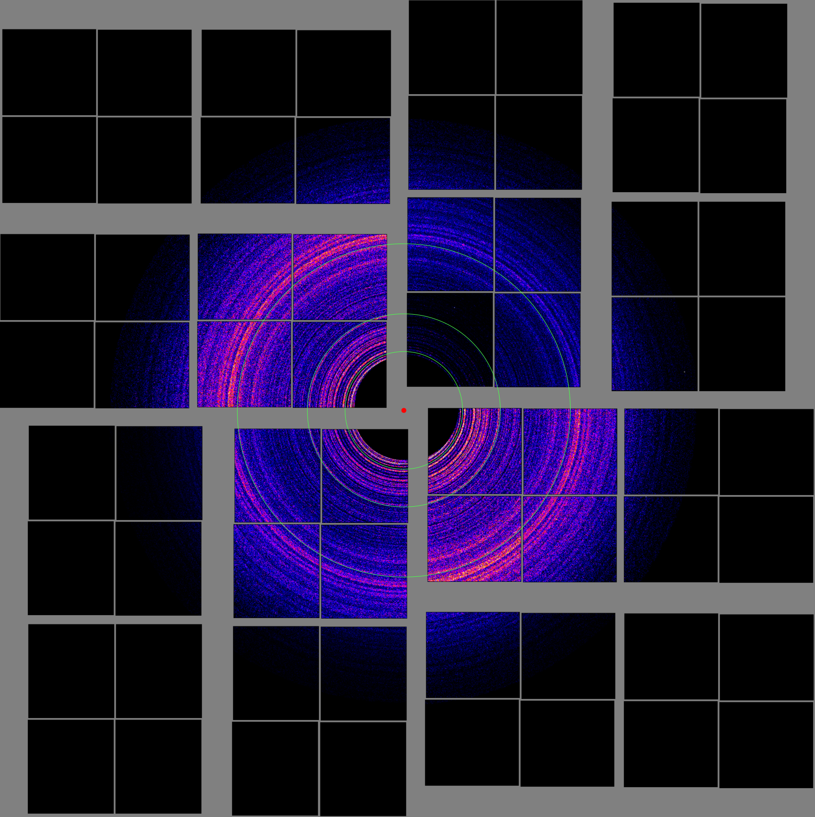
My student Marina tried to “rotate” the geometry – shifting the ss coordinate by 1408, 2816 and 4224 (1,2,3 quadrants). Apparently shift by 4224 gives correct geometry!!! Have a look at the attached shift4224.png. I’ve also indexed the data and checked with geoptimizer – it looks right (except z-offsets).
So please modify in this way your script that makes the geometry from metrology. Don’t forget to rotate the geometry to have visually correct detector – it doesn’t matter for SFX, but nice for users.
Please share the resulting geometry – I’d like to use it.
And I’ll try to add z-offsets to your resulting geometry when I have more data.
And Mikhail, I really want to thank you very much for good optical metrologies! It really saves users a lot of time!
Regards,
Oleksandr. |
However, before solution was found, geoptimizer returned geometry which is significantly different from optical metrology, as shown in movie comparing panels before (from opt metrology) and after optimization.

- It is clear that blind application of geoptimizer may cause >1 mm offset of panels in x-y ...
- It is suggested to use geoptimizer for panels with fixed center and panel orientation in (x,y) from optical metrology and apply optimization for z coordinate and off-plane tilts. Z coordinates were not measured correctly in optical metrology.
- Next optical metrology is expected to be with precise (~10um) Z measurement.
References
- EPIX10KA2M References
- Optical metrology of epix10ka2m.0 from 2018-11-18
- Optical metrology of epix10ka2m.0 from 2020-06-25
- EPIX10KA2M and EPIX10KAQUAD
- EPIX10KA panel flatness measurement
...
Geoptimizer or how geometry can be screwed-up if it is applied blindly
First thanks to Olexandr and Marina for discovering how our geometry should be mapped to data array.
However, as an intermediate step geoptimizer returned geometry which is significantly different from optical metrology, as shown in movie as comparing panels before (from opt metrology) and after optimization.
It is clear that blind application of geoptimizer may cause >1 mm offset of panels...
References
Overview
Content Tools