Page History
| Table of Contents |
|---|
How to Find it
The Different versions of the controls camera viewer is are installed in /reg/g/pcds/controlspyps/pycaqtapps/pulnix6740.latest and camviewer. This directory contains a symbolic link latest to the directory containing the most recent version. The viewer can be run as:
| Code Block | ||
|---|---|---|
| ||
run_pulnixviewer.csh --instrument HUTCH --pvlist CONFIG --camera NUMCAM --cfgdir CFGDIR --rate RATE |
HUTCH is one of the standard hutch names (fully capitalized) , and CONFIG is a viewer configuration file, and NUM . CAM is an optional parameter telling which camera number to view initially (defaulting to zero). the first camera in the configuration file). This can either be an integer index into the configuration file, or part of a camera name (the first camera that matches will be selected). RATE is an optional parameter giving the desired data rate in frames per second. (Generally speaking, this should be no more than 5, but it can be lowered to lessen network traffic.) CFGDIR is another optional parameter giving a directory in which the viewer state will be saved. If it is not specified, the state will be saved in $HOME/.yagviewer. The global state that is saved there includes:
...
- The camera type: one of the reserved words "LIF", "AVG", "IC", "GE", or "GEDREC", optionally followed by a colon and a list of flags. (Currently, the only supported One important flag is is ":D", indicating that the IOC includes a droplet finder.). These words do not refer to the actual type of the camera, but the structure of the IOC that supports it. The three types of IOC currently supported are:
- "LIF" is a camera with an image PV named "LIVE_IMAGE_FULL". The number of columns is given by a PV called "N_OF_COL" and the number of rows is given by the PV "N_OF_ROW".
- "AVG" is a camera similar to "LIF" that also supports on-IOC averaging. In addition to "LIVE_IMAGE_FULL", the averaged image PV is "AVG_IMAGE", and "AVERAGER.A" is the number of frames to average.
- "IC" is a camera with a compressed image PV named "IMAGE_CMPX". This This is the usual type for FEE drop-in cameras. The compressor accepts a region of interest in the PVs ROI_X_SET, ROI_Y_SET, ROI_XNP_SET, and ROI_YNP_SET and produces an image of this region at a resolution of at most 512x512 pixels in IMAGE_CMPX. The pixel values are also given a leftward bit-shift according to the value of the PV "SHIFT". The number or columns is given by the PV "COMPRESSOR.VALF" and the number of rows is given by the PV "COMPRESSOR.VALE".
- "GE" is a gigabit ethernet camera. The image PV is named "ArrayData" and the image dimensions are given by the PVs "ArraySize0_RBV", "ArraySize1_RBV", and "ArraySize2_RBV". If "ArraySize0_RBV" is 3, then this is a color camera with the number of rows in "ArraySize1_RBV" and number of columns in "ArraySize2_RBV". Otherwise, this is a black and white camera where "ArraySize0_RBV" contains the number of rows, "ArraySize1_RBV" contains the number of columns, and "ArraySize2_RBV" is zero.
- "DREC" is a Dehong frame grabber camera. The image PV is the ".ISLO" field and the image dimensions are given by ".CCOL" and ".CROW". This is a strange and special snowflake that is used for the XTCAV camera.
- The base name of the camera PVs. Since some gigabit ethernet cameras have different base names for the control PVs and the image PVs, the rather bizarre syntax "camerabase;controlbase" is supported to allow specifying both of these. (The names above will be appended to this string in order to get the full PV name.)
- The base name of the EVR PVs. If this field is blank, the previously specified EVR will be used.
- The name of the camera to be used in the GUI.
- Optionally, the name of the PV that controls the lens of this camera. It is assumed that this PV takes a value from 0 to 100. However, this parameter has also suffered from feature creep and can be specified as "lens_write_pv;lens_read_pv/minvalue/maxvalue".
There are several camera-type flags that are supported. Most of them are used to modify the "IC" type of camera. These flags include:
- Z denotes a camera with row information in IMAGE:DoPrj.NOVA and column information in IMAGE:DoPrj.NOVB that has an ROI controlled by ROI_X_Start, ROI_Y_Start, ROI_X_End, and ROI_Y_End.
- R denotes a camera with row information in ROI_YNP and column information in ROI_XNP that has an ROI controlled by ROI_X, ROI_Y, ROI_XNP, and ROI_YNP.
- M denotes a camera with row information in IC_YNP and column information in IC_XNP that has an ROI controlled by ROI_X_SET, ROI_Y_SET, ROI_XNP_SET, and ROI_YNP_SET.
To simplify the use of common cameras, directives of the form "include FILEPATH" may also be included in the configuration file. FILEPATH is not quoted in any way, and may either be an absolute path or a path relative to the directory containing the file with the include directive. As most of the hutch camera viewer configuration files are of the form /reg/g/pcds/pyps/config/XXX/camviewer.cfg (where XXX is the hutch identifier), it is expected that most include statements will have the form "include ../YYY/camviewer.cfg", where YYY is some other hutch identifier.
The Viewer GUI
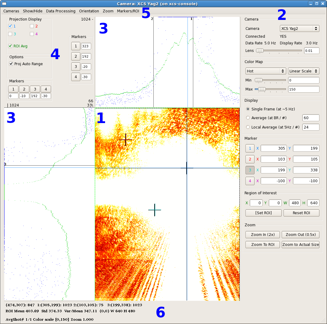
GUI Elements
...
- A dropdown list of cameras to select from.
- The lens control, if this camera has a lens PV.
- The colormap control. The user can select one of five colormaps: HSV, Hot, Jet, Cool, or Gray. Each of these can be set up to be linear, log, or exponential, with user-specified minimum and maximum values.
- Averaging control. The viewer can either display single frames, an on-IOC calculated average (if the IOC supports this), or a locally performed average.
- IOC image control (for camera type "IC" only, not displayed here). If the IOC supports an on-IOC region of interest selection, controls to set the region and the bit-shift are displayed here.
- On-image markers. The current location of the on-image markers are given here. The buttons to the left of these location can be enabled so that left-clicking on the image will set the marker.
Wiki Markup - Droplet finder control. Some IOCs include a droplet finder that has two regions of interest that are examined to find the location of a dark spot (droplet). There are radio buttons that can be used to select one of these regions of interest, and push buttons that can be clicked to either set the viewer ROI from the drop finder ROI, or vice versa. A checkbox allows the viewer to constantly update markers 1 and 2 from the calculated drop locations. Finally, each ROI has a noise floor that can be set to make the algorithm more or less sensitive. (The droplet finder works by projecting the ROI onto both axes, and then fitting a quadratic to the projections. Once the projection is subtracted from the fit, the peak is the droplet, which is located by doing a center of mass calculation. The noise floor is the fraction of the maximum value below which any projected value is considered to be noise and is set to zero.)
- Zoom control. Controls are provided to zoom in, zoom out, zoom to the region of interest, or zoom to the actual image size.
...
Overview
Content Tools