Outline
- Stave Loading Tooling, 19-1 RD53a L1 Stave – .zip - 11 March 2022.zip
- Stave Loading Tooling, 19-1 RD53a L0 Stave
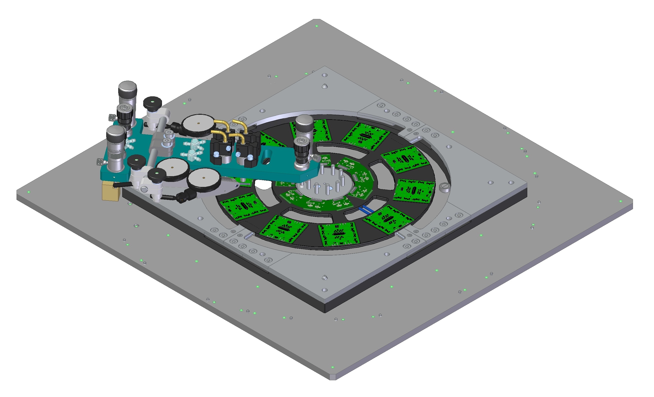
- Ring Loading Tooling, 19-1 RD53a
- Handling Frame, 19-1 RD53a OB L1 Stave
- Shipping Box, 19-1 RD53a OB L1 Stave
Stave Loading Tooling, 19-1
...
L1 Stave
...
Version 2, revised, Stave Loading Tooling
...
Ring loading glue locations drawing drafts (not released):
.zip of all drawings and .step files - 11 March 2022.zip
- Top Level Assembly: REF-
...
...
...
...
...
- In the future, review drawings in Mechanics meeting and release/add to Windchill CAD library, to reduce risk of interface issues.

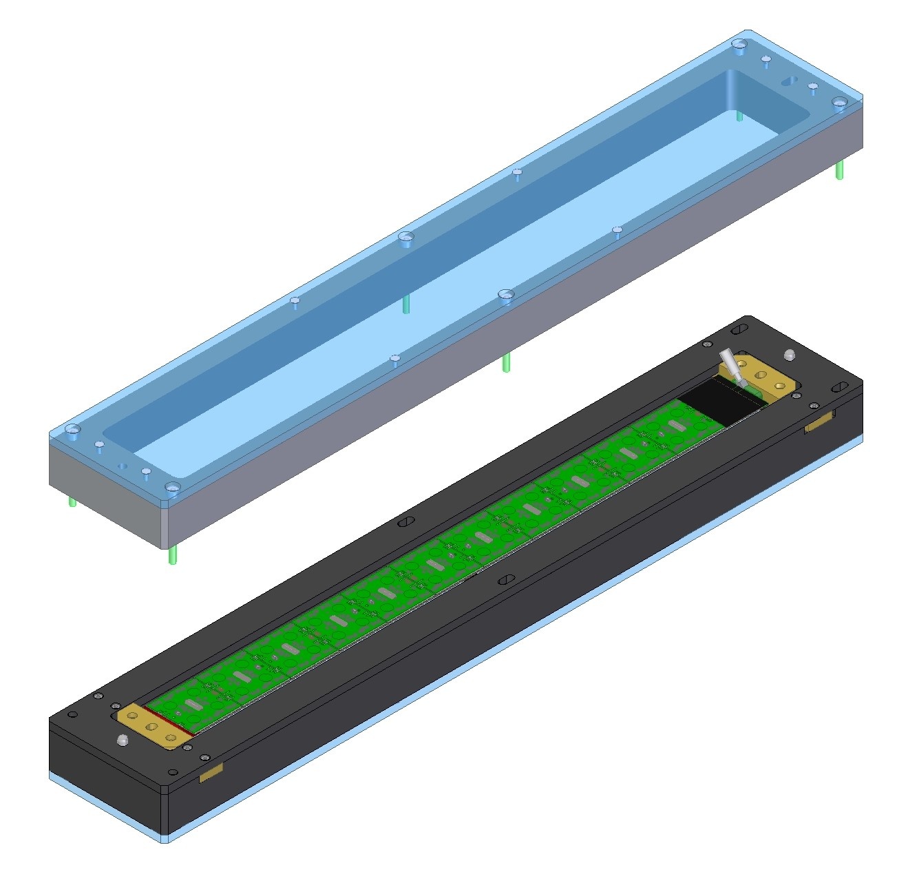
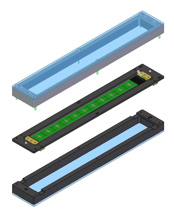
Handling Frame and Shipping Box
Handling Frame and Shipping Box added for Stave. Drawings created (not released).
Drawings (not released):
Handling Frame:
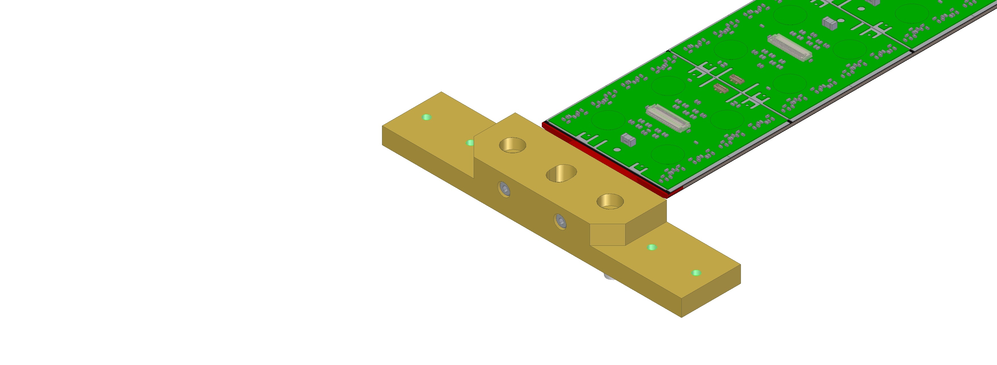
Interface block to join Stave and Handling Frame (not released):

Shipping Box:

Stave Loading Tooling
A design/drawings were made in 2020 (Version 1, deprecated, not released): 19-1 STAVE LOADING TOOLING DRAWINGS 15DEC2020.pdf
- V1 does not include lessons learned more recently.
- Changes for V2: add 2nd set of adjusters, stepped pins, adjustable vacuum pads, handles.
Version 2, revised, Stave Loading Tooling drawings in progress. Drafts (not released) for baseplate (precision pins) and assemblies.
- Loading Bridge: REF-000202287 (LOADING BRIDGE, FIXTURE, 19-1 L1 STAVE).pdf
- Covers for loaded modules: REF-000202337 (COVER SECTION, 19-1 L1 STAVE).pdf
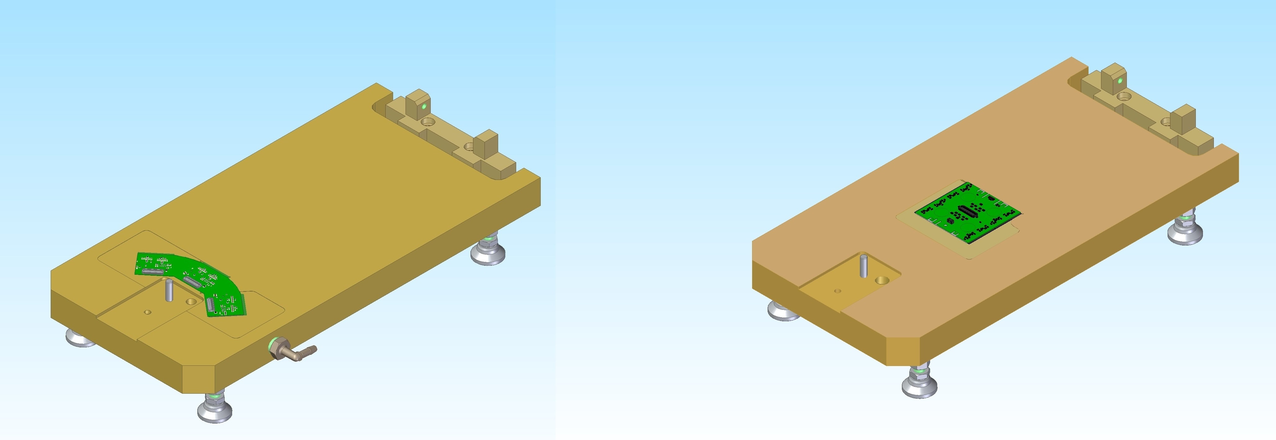
- Pickup table assy: REF-000202485 (PICK UP TABLE, QUAD, 19-1 L1 STAVE LOADING FIXTURE).pdf
- Handling Frame Assembly: REF-000203023 (HANDLING FRAME, L1 STAVE, 19-1).pdf
| Items | Vendor | Date | Response |
|---|---|---|---|
| Parametric USA | 3/7/2022 |
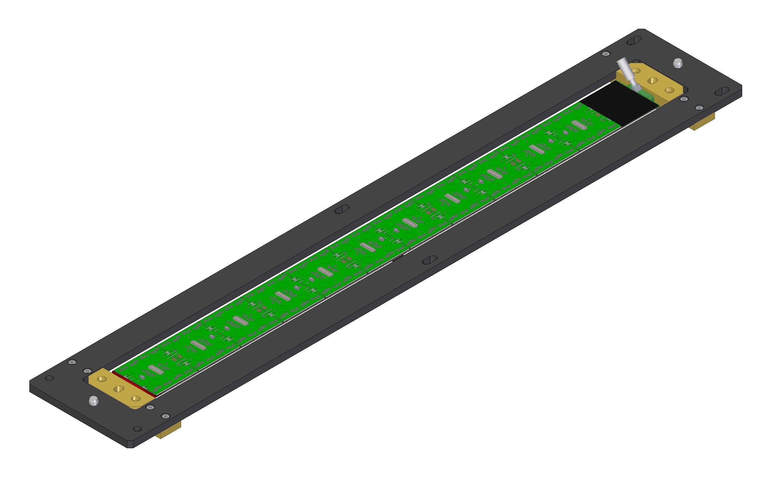
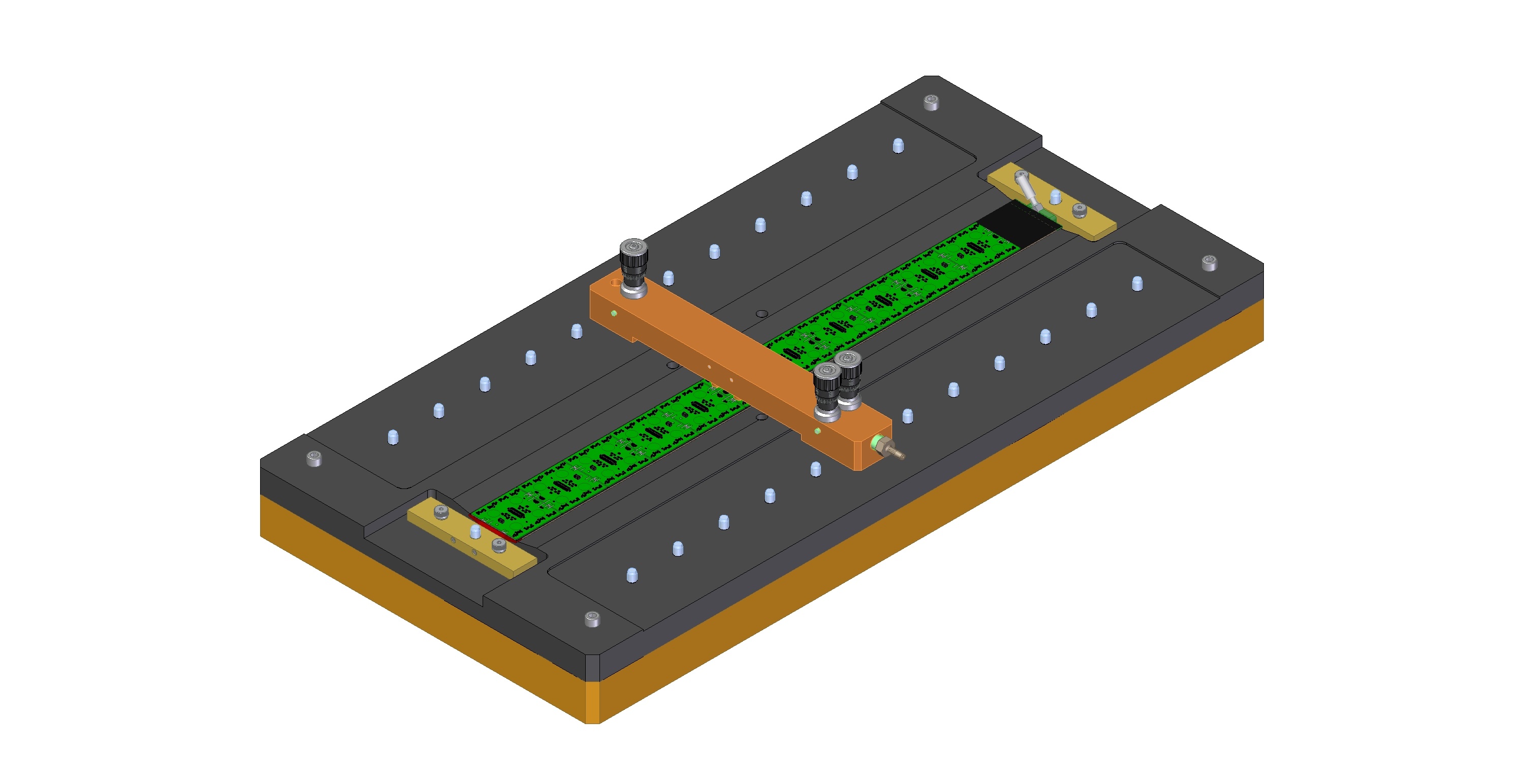
Loading Tooling, L1 Stave:

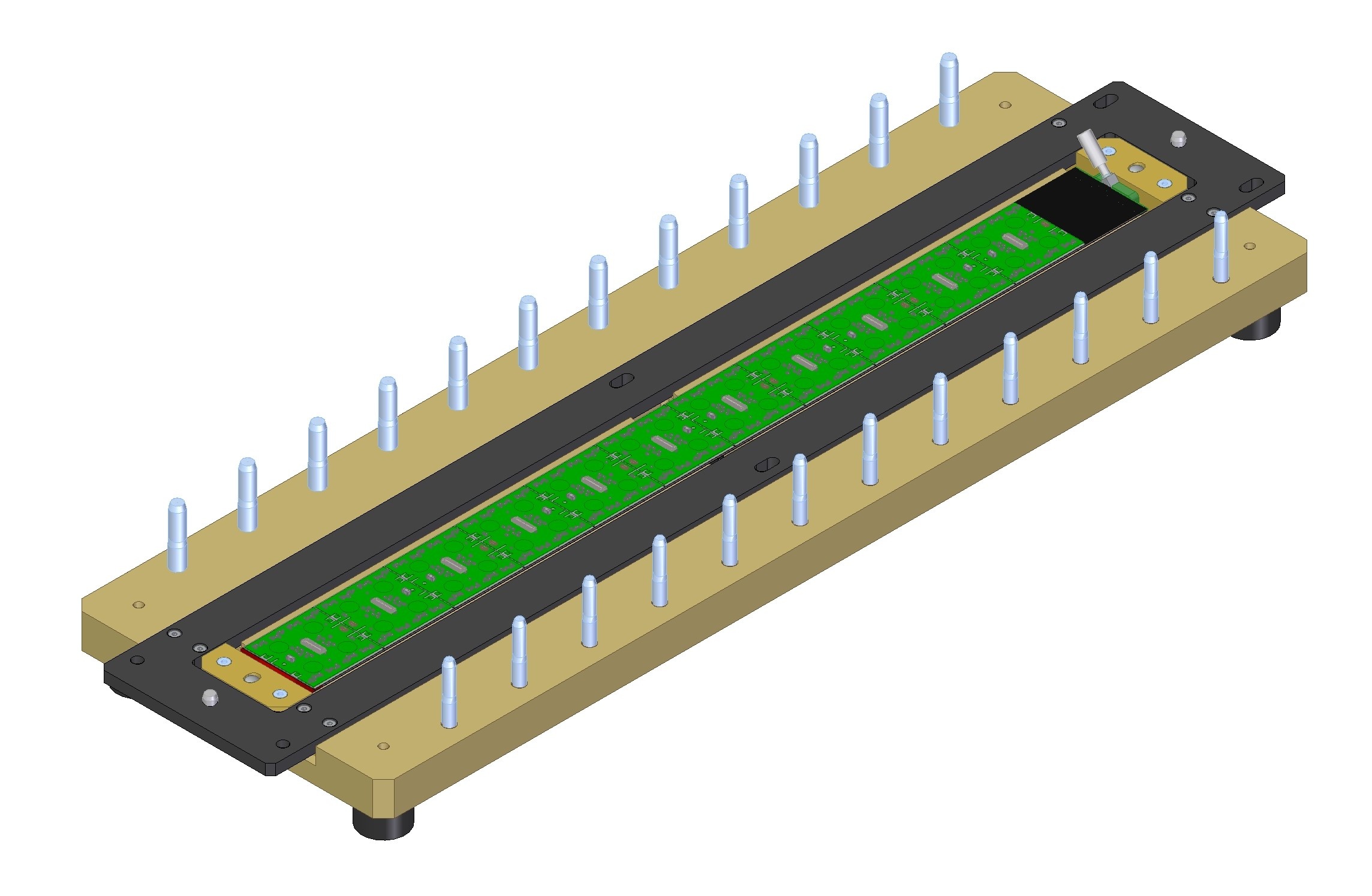

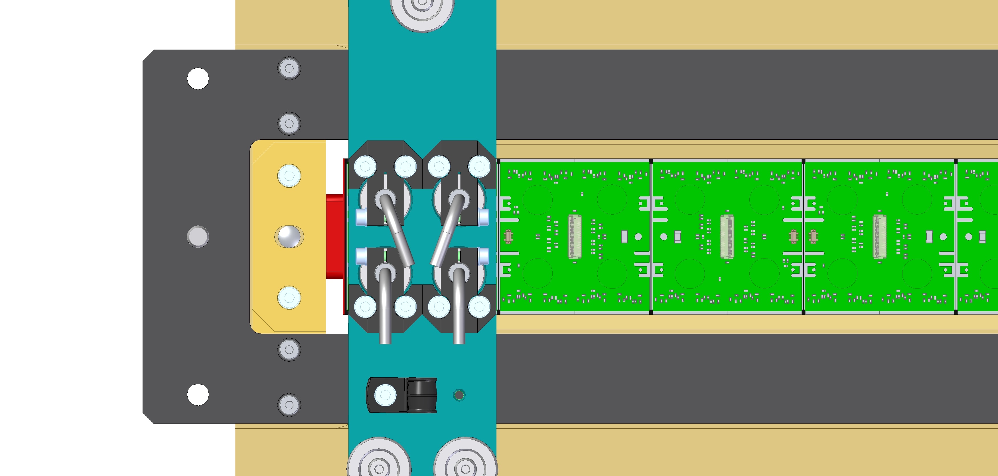

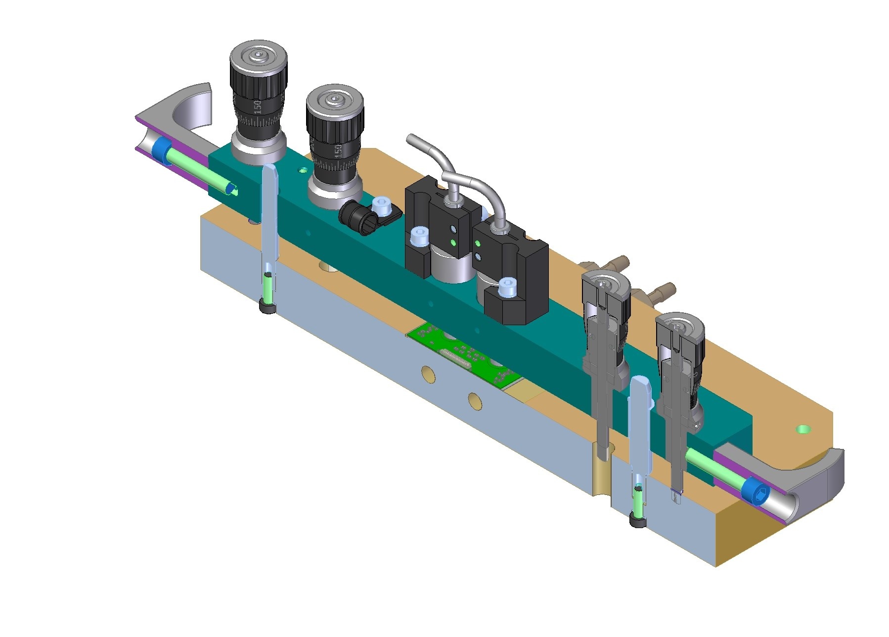
Section view:
Stave Loading drawing drafts (not released):
- Top Leve Assembly: REF-000202041 (LOADING FIXTURE ASSY, 19-1 OB STAVE).pdf
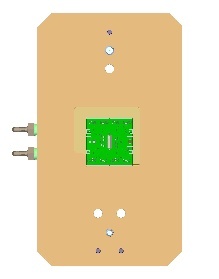
- Baseplate: REF-000203575 (BASEPLATE AND PINS, LOADING FIXTURE, OB STAVE, 19-1, V2).pdf
- Loading Bridge: REF-000202287 (LOADING BRIDGE, FIXTURE, 19-1 OB STAVE).pdf
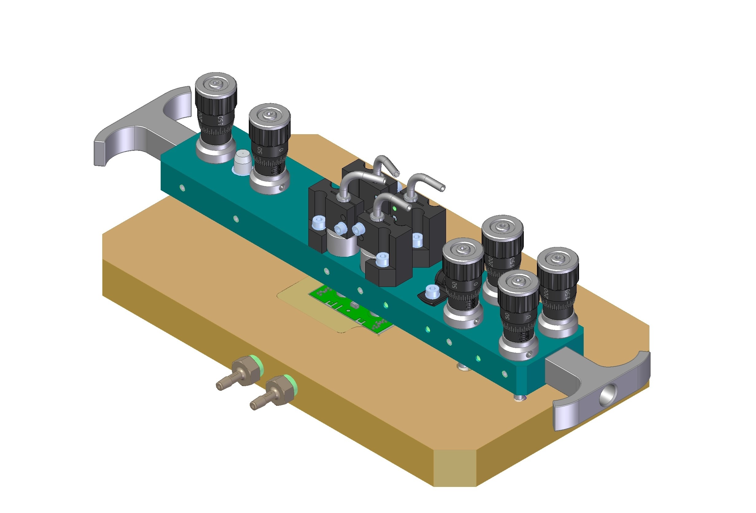
Loading Tooling:
Summary of requirements for loading 19-1 Outer Barrel Stave:
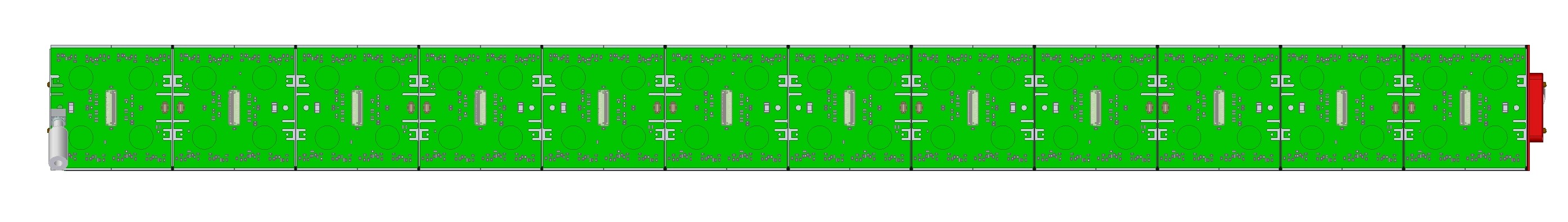
- Load RD53a Quad modules (drawings: 150um, 400um) with connectors oriented as shown in picture above
- Load modules onto 19-1 OB L1 Stave (no drawing yet, preliminary CAD on LBL Windchill site)
- Load without collisions: 200um nominal gap / 100 micron minimum gap between modules (no assembly drawing yet showing modules on stave)
- Glue layer thickness to be 100um -50/+100um
- ESD protection during loading: grounding of tooling
- Mechanical protection of wire bonds during loading: stay clear of wire bonds, handle modules using tooling only, consider covers/shields
- Baseplate to be installed onto glue robot: weight limit 7kg (per manual)
- Stave to be removed from baseplate and transferred to test box for QC testing
Summary of different requirements for loading 19-1 Inner Barrel Stave:
- Load Triplet modules (drawing, .step)
- Load onto 19-1 IB Stave (no drawing yet, preliminary CAD on LBL Windchill site)
- Load without collisions: 200um nominal gap / 100 micron minimum gap between modules (no assembly drawing yet showing modules on stave)
Summary of specifications:
- Closely toleranced pins/bushings – same approach as used for 19-0 tooling
- Requirement: +/-75um module position tolerance in local support coordinate system (per requirements document "ITk Pixel Module Loading Accuracy Requirements" AT2-IP-ES-006-v3)
- Distribute tolerances:
- +/-50um module position relative to loading tooling baseplate coordinate system (to avoid collisions with 100um gap between modules).
- Dowel pins in baseplate – two per module location.
- Bridge to have bushing and slot for precision fit onto dowel pins.
- +/-25um local support position relative to loading tooling baseplate coordinate system (to accurately place modules to meet +/-75um requirement).
- Dowel pin in baseplate – to accurately locate one end of the Stave in Z.
- Tooling to fasten to mounting features on ends of Stave.
- +/-50um module position relative to loading tooling baseplate coordinate system (to avoid collisions with 100um gap between modules).
- Glue with beads to control glue layer thickness
- 100um dia beads, for ~75um glue layer thickness on carbon fiber.
- Loading tooling does NOT control the glue layer thickness.
- Loading bridge to rest on the module's pickup areas (vacuum pad locations) during gluing.
- Loading bridge to have micrometer adjusters to level the tool relative to the baseplate – to apply pressure at all vacuum pad locations during gluing.
- Loading bridge to have micrometer adjusters to level the tool relative to the pickup table – to make good contact between vacuum pads and module.
- Vacuum pads to pick up modules
- Vacuum pads to fit within clear areas on modules.
- Height adjustment of vacuum pads while on pickup table.
- Vacuum to securely hold modules.
- Tolerances:
- Module position relative to loading tooling baseplate (need +/-.050mm):
- Baseplate has:
- Dowel pin, stepped, 6mm OD, h7 tolerance. (Misumi SWPG6-P6-Q5.5-L12-B12-E3-F15)
- Dowel pin, stepped, 8mm OD, h7 tolerance. (Misumi HWPG6-P8-Q7.5-L11-B12-E3-F15)
- Loading bridge has:
- Bushing, 8mm ID, G6 tolerance. (Misumi JBAUN8-20)
- Machined slot, 6mm internal width, G6 tolerance.
- Baseplate has:
- Module position relative to loading tooling baseplate (need +/-.050mm):
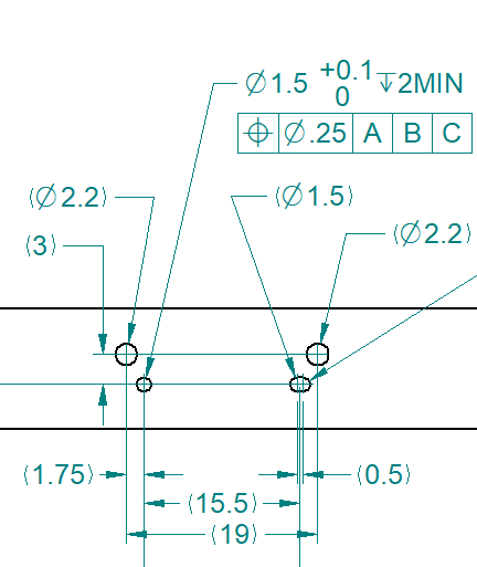
Dimensioning scheme changed to hole-to-hole tolerancing (instead of hole-to-edge):
| Tolerance Item | Where Used | Tolerance (mm, Dia.) |
| Pick-up Table Edge Repeatability(for successive modules) | Locating Module to Pickup Table (repeatability of lining up module to machined edges) | 0.012025 |
| Bridge Pickup Table Bushing ID | Locating Loading Bridge to Pick-up Table | 0.012019 |
| Bridge Pick-up Table Pin OD | Locating Loading Bridge to Pick-up Table | 0.012 |
| Pin Location | Locating Loading Bridge to Pick-up Table | .020 |
| 015 | ||
| Baseplate Hole Bridge Bushing ID | Locating Loading Bridge to Loading Fixture | 0.012025 |
| Baseplate Bridge Pin OD | Locating Loading Bridge to Loading Fixture | 0.012015 |
| Pin Baseplate Hole Location | Locating Loading Bridge to Loading Fixture (hole locations dimensioned as +/-.04 from adjacent hole, i.e. up to -.02 per hole) | 0.020 |
Total: | .100mm 119mm (+/-.050mm060mm) | |
| Root Sum Square: | .039mm 050mm (+/-.019mm025mm) |
Stave position relative to loading tooling baseplate
...
:
| Tolerance Item | Where Used | Tolerance (mm, Dia.) |
| Pin Location | Locating Stave to BaseplateLoading Bridge to Loading Fixture (hole locations dimensioned as +/-.04 from adjacent hole, i.e. up to -.02 per hole) | 0.020.025 |
Pick-up Table Edge Accuracy (absolute position) | Locating Module to Pick-up Table *choose loading tooling baseplate coordinate system to line up with 1st module*this item affects all modules equally so does not affect gap/distance between modules | 0.025060 |
| Total: | 0.080mm (+/-.040mm) | |
| Root Sum Square: | 0.050mm 063mm (+/-.025mm032mm) |
- Total for all:
- Limit: +/-.075mm100mm
- Root sum square: +/-.040mm
- Requirement: +/-.026mm150mm
- Module Nominal Spacing (for 19-1 L1 Stave): .250mm (nominal gap)
- Worst case clearance: 0.012mm
- Clearance with RSS tolerance (3σ): 0.180mm
A design/drawings were made in 2020 (Version 1, deprecated, not released):
- 19-1 STAVE LOADING TOOLING DRAWINGS 15DEC2020.pdf
- V1 does not include lessons learned more recently.
- Deprecated V1 design:
- Changes for V2: add 2nd set of adjusters, stepped pins, adjustable vacuum pads, handles.
Some past presentations:
- 30 March 2021: Tooling and Plans for Loading, 19-0/1, Stave and Ring
Module and Stave dimensions
Compare:
- Module width (ensure all fit on Stave)
- Module FE chip dimensions (re-use tooling)
| Module | FE Chips Dimensions (mm) | Width (mm) | Reference |
|---|---|---|---|
| RD53a Quad 150um | 42.137 x 40.335 | 41.1 | |
| ITkPixV1 150um | 42.2 x 40.3 | 41.1 | |
| ITkPixV1 100um | 42.2 x 40.3 | 40.7 | |
| RD53a Linear Triplet | 61.29 |
Can load up to 11 (of 12) modules onto 19-1 Stave prototype:
- Stave length (flat region): 491.6mm
- RD53a (19-1)
- Modules length: 12*(41.1mm+.2mm)=495.6mm
- 12 modules would result in 4mm overhang beyond end of stave. Plan not to load full stave anyway due to module availability.
- ITkPixV1 100um
- Modules length: 12*(40.7mm+.2mm)=490.8mm
- Appears to fit onto Stave. Module pitch (40.9mm) different from 19-1 pitch (41.3mm) so would need to make a new baseplate with this pitch.
- RD53a Triplet (19-1)
- Modules length: 8*(61.29mm+.15mm)=491.52mm
- Appears to fit onto Stave.
Stave Loading Tooling, 19-1 IB Stave
Requirements - see L1 Stave requirements above.
Summary of different requirements for loading 19-1 Inner Barrel Stave:
- Load Triplet modules (drawing, .step)
- Load onto 19-1 IB Stave (no drawing yet, preliminary CAD on LBL Windchill site)
- Load without collisions: 200um nominal gap / 100 micron minimum gap between modules (no assembly drawing yet showing modules on stave)
Design concept: modify design of 19-1 L1 Stave tooling to match Triplet dimensions and pickup areas
Ring Loading Tooling
Ring loading glue locations drawing (not released): REF-000160474 (LOADING FIXTURE, 19-1 RING).pdf
Ring Loading Tooling Drawings and .step files:
- 19-1 Ring.zip
- In the future, plan to review drawings in Mechanics meeting and release/add to Windchill CAD library, to reduce risk of interface issues.
Handling Frame and Shipping Box
Drawings (not released): REF-000202479 (SHIPPING AND STORAGE FIXTURE, L1 STAVE, 19-1) CHECKPRINT 14FEB2022.zip
Handling Frame with 19-1 L1 Stave:
Interface block to join Stave and Handling Frame (drawing not released):
Shipping Box: