Page History
...
- nda = calib_epix10ka_any(det, evt)
- nda *= det.mask(par, calib=False, status=True, edges=True, central=True, width=1, wcentral=1, mode=0)

Manual alignment on 2019-05-06
Data for alignment
Ring-data (npy) arrays were provided by Silke, available under
- /reg/g/psdm/detector/alignment/epix10ka2m/calib-mfx-epix10ka2m-01-2018-11-15
Manual alignment tool
Manual Detector alignment tool (geo) is used for alignment. There is no automated geometry optimization in this tool.
Initial geometry and data files
Alignment is started with the best geometry file obtained after optical metrology measurements for two quads, like
/reg/d/psdm/xcs/xcsx35617/calib/Epix10ka2M::CalibV1/XcsEndstation.0:Epix10ka2M.0/geometry/398-398.data
Alignment procedure
Quads' x0,y0 - center positions ONLY have been tuned as explained here:
1) Q0 and Q1 were moved together relative to the image center, because their geometry is constrained from optical metrology.
2) then Q2 and Q3 were moved independently in order to get consistent "to my eye" image relative to a set of drown circles.
Geometry for panels inside Q2 and Q3 is set from design geometry, and I do not feel that could do better job moving panels in quad.
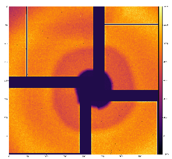
There are some regular alignment issues with this detector; if I tune nicely (with precision ~ pixel size) rings in the middle of radial range,
then internal and external rings may be misaligned. This may be due to small tilt of the detector or non-accounted z position of panels
w/o optical metrology.
Results
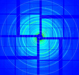
Resulting geometry for this data looks like on attached image.
All files are available under
- /reg/g/psdm/detector/alignment/epix10ka2m/calib-mfx-epix10ka2m-01-2018-11-15
Recommendation for further geometry improvement
The only reliable procedure to get correct detector geometry is an 3-d optical metrology of entire detector.
After that one would need to adjust precisely
1) detector center relative to image with rings
2) sample-to-detector distance
3) detector plane tilts.
References
- EPIX10KA
- Jungfrau and Epix10ka Calibration
- Detector alignment tool
- /reg/g/psdm/detector/alignment/epix10ka2m/calib-mfx-epix10ka2m-01-2018-11-15
Overview
Content Tools