Nelson, Silke <snelson@slac.stanford.edu>
Thu 3/18/2021 2:44 PM
Hi all,
Mikhail and Chuck are the local experts on the detector geometry and they have kindly agreed to look at our data to see what, if any, improvements to the currently use geometry we can achieve.
They have reminded us to make sure that the detector is not flat and you need to take the z-coordinate as obtained through the geometry might need to be taken into account. I believe that this was done for xpplu8318, but that the result still allowed for improvements.
I have not been able to find pictures with rings in the elog for the xcslv9718 or xcsx39718, Tim could you let Chuck and Mikhail know where to look?
I have looked at the log and believe examples with rings could be obtained from:
xpplu8318, run 319 and 323
Thies, please let us know if there are better runs t be used or a list of runs where its most obvious that improvements might be possible.
Thank you,
Silke

Albert, Thies Johannes <thies.albert@uni-due.de>
Fri 3/19/2021 8:18 AM
Hi all,
thank you in advance for your help.
As Silke wrote in xpplu8318 we took the x-, y- and z- coordinate as they are stored in the HDF5-files into account.
I think all Al-calibration runs are good to look at. These are #175, #206, #217, #239, #276, and #319. There are rings visible on all parts of the detector. I think especially in Run #239 its most obvious that improvements might be possible.
Best regards
Thies

--
Thies Johannes Albert
Fakultät für Physik
Universität Duisburg-Essen
Lotharstraße 1
Raum MG152
47048 Duisburg

Tel: +49 (0)203 379  4563
Fax: +49 (0)203 379 4555


Dubrovin, Mikhail
Mon 3/22/2021 5:41 PM
Hi Thies,
There is a couple of questions about z coordinate.
1) what is the (approximate) distance from IP to the detector sensor plane in exp=xpplu8318:run=239 ?
2) >> in xpplu8318 we took the x-, y- and z- coordinate as they are stored in the HDF5-files
If I understand correctly, you use files like
 /reg/d/psdm/XPP/xpplu8318/hdf5/smalldata/xpplu8318_Run239.h5
This file contains x and y arrays as
Dataset: ds.name         =  /UserDataCfg/epix10k2M/y
However, in this file I do not see any dataset for z coordinate.
What exactly was used as z ?
Mikhail


Nelson, Silke <snelson@slac.stanford.edu>
Mon 3/22/2021 8:47 PM
Hi Mikhail,
you can find the numbers e.g. in the hdf5 file for run 333. As we do not change the geometry during an experiment, Thies et al have created their own geometry from the information provided in the later hdf5 files thus getting around the need to reprocess everything. The distance to sample used for run 239 was 69.88429 which was extracted from run 271 (as far as I could see from the translation code).
Best,
Silke


Albert, Thies Johannes <thies.albert@uni-due.de>
Tue 3/23/2021 3:09 PM
Hi Mikhail,
the correct file location is /reg/d/psdm/xpp/xpplu8318/scratch/xpplu8318_Run239.h5
There you’ll find the x-, y-, and z-coordinates. We calculated the distance to 0.06962 m. This agrees well with what the xpp-staff told us.
Best,
Thies


Nelson, Silke <snelson@slac.stanford.edu>
Thu 3/25/2021 11:13 AM
Hi Thies,
I remember that you gave me the rotations of the detector you had two use to make the azimuthal averaging code work again that pyFAI returned with the detector-sample distance. It would be great if you could give them to us (really Mikhail) again, ideally also with the definition as Mikahil does not think in term of my inherited azimuthal-averaging code.
Thank you,
Silke


Albert, Thies Johannes <thies.albert@uni-due.de>
Thu 3/25/2021 12:14 PM
Hi Silke, hi Mikhail,
yes, we did the calibration with pyFAI and used the pyFAI.ai.getFit2D() method to convert the values for your azimuthal-averaging code. These values are for Run 239:
xCen=46782.274069
yCen=61947.3516318
tx=71.5677183903
ty=1.26828682272
dist_to_sample=69.6370601323
Attached I send you the poni-file from pyFAI and the detector geometry in Nexus-convention as we calculated from the x-, y-, z- coordinates that are stored in the HDF5-files. These are the centers of the pixels; pyFAI uses the pixel-corners so we took this into account.
We integrate the data with pyFAI using this poni-file and this nexus-detector-file. For this we are mapping the 16x352x384 detector data-array to a 2D-array using the ix and iy values from the HDF5-File. With the nexus-detector-file pyFAI uses the correct x-, y-, z-coordinates for each pixel.
Thank you for your efforts,
Thies

Nelson, Silke <snelson@slac.stanford.edu>
Sat 3/27/2021 11:29 AM
Hi Mikhail,
For other reasons I looked at some recent XCS data and see runs with nice rings in xcslv9617, e.g. run 191. You can look at average images for the epix10k2M in the run summary plots at:
https://pswww.slac.stanford.edu/lgbk/lgbk/xcslv9718/#summaries
The parameters used for the azimuthal average here are either (from code)
    ret_dict['center'] = [-7466.1,9931.8] #micron
    ret_dict['dis_to_sam'] = 43.746  #mm
From hdf5:
    ret_dict['center'] = [57.55931, 484.5105] #micron
    ret_dict['dis_to_sam'] = 44  #mm
Best,
Silke


Albert, Thies Johannes <thies.albert@uni-due.de>
Mon 3/29/2021 8:09 AM
Hi Mikhail,
in addition to the detector geometry I have a question regarding the sensitivity of the detector for photons incoming at high angles (meaning 2Theta > 60° in our case). When I look at the absorption in Si for 17.769 keV then I get a factor of about 1.8 for 2Theta=60° in comparison with 2Theta=0°. Is this a valid consideration and have you thought about that?
Thank you,
Thies


Dubrovin, Mikhail
Mon 3/29/2021 9:45 AM
Hi Thies,
I am on vacation today.
There is some modest progress with my understanding of geometry in your case.
I will send you my results probably tomorrow.
>>  Is this a valid consideration and have you thought about that?
Yes, off cause, it is valid. Strictly speaking it is not about geometry but is about physics of absorption. I guess we can't fix it with changing something in geometry description.
Mikhail


Albert, Thies Johannes <thies.albert@uni-due.de>
Mon 3/29/2021 11:16 AM
Hi Mikhail,
thank you for the quick response.
My „in addition to the detector geometry“ was more meant as a „beside the geometry“…
To me it is clear that this point, even if it is possible, should be treated outside the geometry. I think that the absorption leads to the fact that we get a peak-broadening for large angles. But this is, as far as I can see, small compared to the energy fluctuations of the FEL, so it can be neglected. In terms of sensitivity, though, the question is how do I account for that? I can calculate the X-ray absorption coefficient for 500 µm Si. Is this then a correlation of coeff/cos(2Theta)? This is not clear to me.
Also, will a signal be generated when a photon has penetrated the silicon layer and is absorbed in the electronics behind it?
Thies
P.S. Please let me know if you need anything else from me.


Nelson, Silke <snelson@slac.stanford.edu>
Mon 3/29/2021 11:19 AM
Adding detector folks as this falls more into their expertise.
Best,
Silke
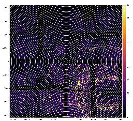
Issue on image
dataset exp=xpplu8318:run=239
detname XppGon.0:Epix10ka2M.0
alias epix10k2M
used geometry file /reg/d/psdm/xpp/xpplu8318/calib/Epix10ka2M\:\:CalibV1/XppGon.0\:Epix10ka2M.0/geometry/0-end.data
command for averaging/max of data: det_calib_ave_and_max exp=xpplu8318:run=239 XppGon.0:Epix10ka2M.0 1000 0 None DEBUG
command to plot image of the data array for specified geometry:
geometry_image -g 2020-06-25-geometry-test.txt -a det-calib-max-e10000.txt --amin 18 --amax 36 -R50 --zplane -70000
IMPORTANT: detector is in short distance ~70mm from IP.
For this study pixel 3-d coordinates are always projected to the 2-d plane transverse to the beam --zplane -70000
Default geometry
RECENT 0 CAMERA 0 0 0 0 270 0 0 0.00000 0.00000 0.00000
Re-centered geometry
RECENT 0 CAMERA 0 -47000 -62000 0 270 0 0 0.00000 0.00000 0.00000
- image of data after re-cenering
- r vs. phi projection
- x pixel coordinate
- y pixel coordinate

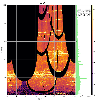


Issue
- central rings are concentric, while peripheral are not concentric
- detector is tilted relative x and y axes
Reason
- most likely detector is not orthogonal to the beam. This parallax effect is magnified by the short IP-to-detector distance.
- it seems problematic to tune tilts around x and y together.
- in stead of apply rotation around two axes x and y we may select the major tilt axis by rotating detector around z to get tilt for one of the axis y or x.
- then, tune tilt around one axis.
- then apply backward rotation around z.
Rotation around Z
it looks like optimal rotation angle around z would be ~60deg:
RECENT 0 CAMERA 0 -47000 -62000 0 270 0 0 0.00000 0.00000 0.00000
TILTZ 0 RECENT 0 0 0 0 60 0 0 0.00000 0.00000 0.00000


Variation of tilt around y axis
RECENT 0 CAMERA 0 -47000 -62000 0 270 0 0 0.00000 0.00000 0.00000
TILTZ 0 RECENT 0 0 0 0 60 0 0 0.00000 0.00000 0.00000
TILTY 0 TILTZ 0 0 0 0 0 0 0 0.00000 1.00000 0.00000
TILTX 0 TILTY 0 0 0 0 0 0 0 0.00000 0.00000 0.00000
IP 0 TILTX 0 0 0 -69620 0 0 0 0.00000 0.00000 0.00000
r-phi projections for tilt angle around y (deg)
optimal angle is in between 1 and 1.2 deg.


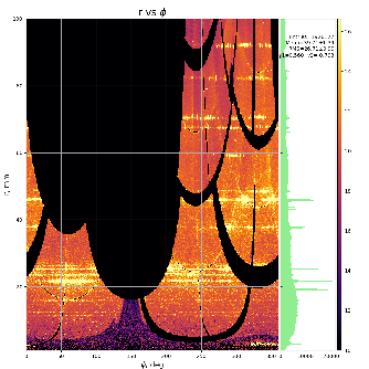


Solution for geometry
after re-centered, rotated around z by 60 deg and tilted around y 1.1 deg apply backward rotation around z by -60 deg:
RECENT 0 CAMERA 0 -47000 -62000 0 270 0 0 0.00000 0.00000 0.00000
CORRY 0 RECENT 0 0 0 -69620 60 0 0 0.00000 1.10000 0.00000
IP 0 CORRY 0 0 0 0 -60 0 0 0.00000 0.00000 0.00000


Geometry file
/reg/g/psdm/detector/alignment/epix10ka2m/calib-xxx-epix10ka2m.0-2020-06-25/2020-06-25-geometry-epix10ka2m-tilted-y.txt
Hasty conclusion
it works!
References