Introduction
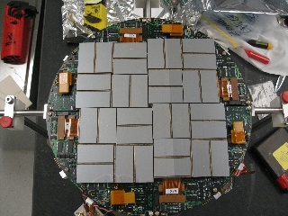
Cornell SLAC Pixel Array Detector (CSPAD) is an imaging X-ray detector made of silicon sensors (2x1) covering about 20x20cm² surface, as shown in the plot:
Pixel coordinates in 2x1 sensor chip are known with sub-micrometer precision. Construction of the detector allows significant freedom in relative positions of 2x1 sensors. To get precise pixel positions in the detector the 2x1 sensor coordinates needs to be calibrated. In this note we describe geometry of the CSPAD detector, optical and quad alignment procedure, parameters, and software providing access to precise geometry information.
2x1 Sensor Geometry
The 2x1 sensor geometry was tested with microscopic measurement. Two slides from Chris Kenney's presentation shows the pixel sizes:
![]()
![]()
The same slides in PDF format.
Important 2x1 features:
- Number of rows x columns = 185 x 388. (In DAQ notation of rows and columns is interchanged...)
- Most of pixels have size 109.92 x 109.92 um².
- Gap between two ASICS is covered by the two rows of elongated pixels with size 109.92 x 274.8 um².
- Two versions of sensors have different dimensions between corners, so it is reasonable to define pixel coordinates w.r.t. the sensor center.
Optical measurement
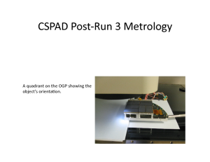
Optical measurement is maintained by Chris Kenney. Detector or its quad is installed on microscope table and 3-d coordinates of all 2x1 sensor corners are measured with precision about 8um (RMS) in x-y plane. All corners in the measurement are numerated in arbitrary order. It is expected that numeration order should be the same for different measurements. This procedure depends on CSPAD construction;
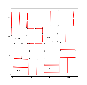
- For CSPAD with movable quads (i.e. for CXI) optical measurement is done separately for each quad. The numeration of corners is shown in the plot:
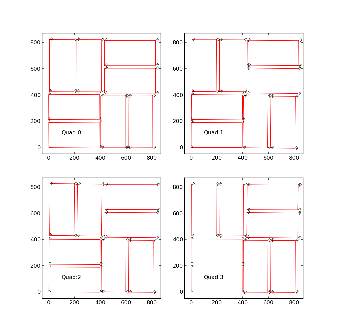
The same plots in PDF format: CSPAD quad metrology and CSPAD pixel layout in quads.
For each quad measurement is started from the point #1 which in assembled detector is closest to the beam. The 1-st point (x,y,z) coordinates are re-set to (0,0,0) in the beginning of measurements. At the end, it is checked that the 1-st point coordinates are reproduced within precision of measurement.
The order of points in optical measurement does not coincide with numeration of 2x1 in DAQ, as shown in the plot (and in PDF file):
![]()
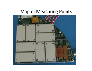
- For CSPAD with fixed quad geometry (i.e. for XPP) optical measurement is done for entire detector. The numeration of corners in this case is shown in the plot:
The 1-st corner of the 3-rd quad (x,y,z) coordinates are re-set to (0,0,0) in the beginning of measurements. At the end, it is checked that the 1-st point coordinates are reproduced within precision of measurement.
Corner coordinates are measured in micrometers (um) and are saved in the xlsx format table, also containing numeration of quads and points. Then, xlsx format table is converted to the text file format in order to use it in python script.
Example of tables for CXI:
Example of tables for XPP:
- Metrology in XLSX
- Metrology in TXT Python script converts this table to the table with standard numeration of points in quads:
- Metrology in standard TXT
Then, text table with "standard" numeration of points in quads is feed to the python script which provides quality check of optical measurement and evaluates the alignment parameters for quads. In the beginning, this script changes the numeration of points adopted in optical measurement to numeration of 2x1 used in DAQ. Further, all calibration parameters are associated with numeration of 2x1 sensors and quads in DAQ.
Quality Check Procedure
For quality check of optical measurement we calculate
S1 - 1st short side length of 2x1
S2 - 2nd short side length of 2x1
L1 - 1st long side length of 2x1
L2 - 2nd long side length of 2x1
D1 - 1st diagonal of 2x1 between corners 1 and 3
D2 - 2nd diagonal of 2x1 between corners 2 and 4
dS and dL are the deviations of the 1st and 2nd corner along the short and long sides, respectively. The sign of all dS are chosen in order to provide correct sign for the tilt angle (the same direction for all 2x1 sensors).
<dS/L> - the tilt angle of 2x1 averaged over two sides in radians.
angle(deg) - the same angle in degrees.
dD = D1 - D2
d(dS) = dS1 - dS2
d(dL) = dL1 - dL2
dz3(um) - signed distance from 2x1 sensor plane and corner 3, where the 2x1 sensor plane contains the corner points p1, p2, and p4. This plane is defined by the vectors v21=p2-p1, v41=p4-p1, and their orthogonal vector
vort = [v21 x v41].
Scalar product with normalization defines the distance from point 3 to the 2x1 plane containing 3 other points:
dz3 = (v31 * vort) / |vort|.
Quality check parameters expected for perfect geometry:
S1=S2, L1=L2 - the 2x1 sides should have equal length and width,
D1=D2 - the 2x1 diagonals should be equal,
dS1 = dS2 ? (388/185)*dL1 = (388/185)*dL2 - tilt angle should provide consistent deviation for all corners,
dD=0, d(dS)=0, and d(dL)=0 - within precision of measurement.
dz3(um) = 0
Everything, excluding <dS/L> and angle(deg), are in micrometers.
Example of the table with quality check results:
pair:        S1      S2     dS1     dS2        L1      L2     dL1     dL2    <dS/L>  angle(deg)      D1      D2      dD   d(dS)   d(dL)    dz3(um)

Quad  0
pair: 0   20891   20913     200     222     43539   43541    -102    -100    0.00485    0.27766   48298   48297       1     -22      -2      2.981
pair: 1   20910   20894     293     277     43540   43535    -127    -132    0.00655    0.37506   48302   48289      13      16       5    -23.986
pair: 2   20890   20906      99      83     43536   43536      42      42    0.00209    0.11976   48290   48293      -3      16       0     -3.034
pair: 3   20897   20895     131     133     43545   43543      65      63    0.00303    0.17369   48299   48297       2      -2       2      6.003
pair: 4   20911   20896     -30     -45     43549   43547      17      15   -0.00086   -0.04934   48303   48306      -3      15       2     -5.994
pair: 5   20901   20898      10       7     43540   43544      -8      -4    0.00020    0.01119   48296   48299      -3       3      -4      9.993
pair: 6   20904   20903     104     105     43536   43540      55      59    0.00240    0.13752   48302   48290      12      -1      -4     52.002
pair: 7   20901   20901      -7      -7     43545   43543      -3      -5   -0.00016   -0.00921   48299   48301      -2       0       2     14.001

Quad  1
pair: 0   20913   20914    -343    -342     43540   43550     165     175   -0.00787   -0.45066   48313   48303      10      -1     -10    -24.002
pair: 1   20898   20901    -145    -142     43548   43551      62      65   -0.00330   -0.18880   48300   48309      -9      -3      -3    -23.005
pair: 2   20895   20903    -151    -159     43535   43532     -74     -77   -0.00356   -0.20400   48289   48291      -2       8       3    -17.995
pair: 3   20872   20909    -235    -272     43341   43354     -37     -24   -0.00585   -0.33507   48201   48036     165      37     -13    -13.010
pair: 4   20940   20904    -455    -491     43527   43554     214     241   -0.01086   -0.62242   48309   48309       0      36     -27      1.101
pair: 5   20910   20903    -302    -309     43546   43546     145     145   -0.00702   -0.40196   48304   48307      -3       7       0      6.016
pair: 6   20901   20919    -421    -439     43529   43539    -213    -203   -0.00988   -0.56593   48296   48298      -2      18     -10     -8.026
pair: 7   20907   20907    -452    -452     43548   43539    -201    -210   -0.01038   -0.59475   48315   48294      21       0       9     -8.982

Quad  2
pair: 0   20914   20914     -25     -25     43536   43540      10      14   -0.00057   -0.03290   48300   48300       0       0      -4    -11.013
pair: 1   20901   20897       7       3     43546   43536      -1     -11    0.00011    0.00658   48293   48300      -7       4      10      4.036
pair: 2   20899   20903    -256    -260     43533   43539    -127    -121   -0.00593   -0.33954   48293   48294      -1       4      -6     -1.023
pair: 3   20912   20904    -210    -202     43540   43547    -106     -99   -0.00473   -0.27106   48300   48306      -6      -8      -7     24.004
pair: 4   20910   20903    -543    -550     43535   43536     261     262   -0.01255   -0.71923   48298   48299      -1       7      -1      0.004
pair: 5   20904   20905    -241    -240     43538   43544     111     117   -0.00552   -0.31647   48298   48301      -3      -1      -6     -6.024
pair: 6   20903   20902      21      22     43539   43543       8      12    0.00049    0.02829   48298   48298       0      -1      -4      8.999
pair: 7   20902   20903      82      81     43546   43547      35      36    0.00187    0.10723   48300   48306      -6       1      -1      9.995

Quad  3
pair: 0   20902   20898     -82     -86     43536   43543      30      37   -0.00193   -0.11054   48289   48302     -13       4      -7      1.994
pair: 1   20900   20904      79      83     43548   43541     -35     -42    0.00186    0.10658   48301   48301       0      -4       7    -17.993
pair: 2   20912   20894     181     199     43536   43535      97      96    0.00436    0.25005   48298   48289       9     -18       1     10.011
pair: 3   20912   20905     119     126     43539   43538      57      56    0.00281    0.16121   48296   48301      -5      -7       1    -16.000
pair: 4   20894   20912    -454    -436     43534   43545     212     223   -0.01022   -0.58560   48303   48296       7     -18     -11      2.023
pair: 5   20906   20919    -336    -323     43527   43535     155     163   -0.00757   -0.43369   48295   48294       1     -13      -8      5.993
pair: 6   20902   20905    -203    -206     43537   43525     -89    -101   -0.00470   -0.26916   48293   48287       6       3      12      2.981
pair: 7   20900   20897    -140    -137     43539   43544     -68     -63   -0.00318   -0.18225   48298   48296       2      -3      -5     29.997
This quality check works well to catch significant typos in input table. In case of obvious typos input table can be corrected. When the quality check is passed successfully the alignment parameters are saved and deployed under the calib.
Summary for 2x1 flatness check: mean and standard deviation of the minimal distance between point3 and the plane containing points 1,2, and 4:
Mean and standard deviation [um]: 0.376 +- 15.818
Alignment parameters from optical measurement
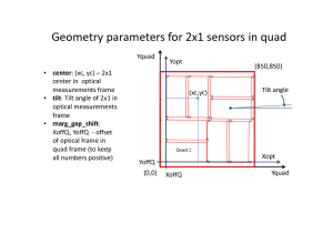
From optical measurement we extract coordinates of the center of each 2x1 sensor and its tilt angle, that populates the calibration types center and tilt, respectively.
The center coordinates are evaluated as an averaged over 4 corners measurements for each axis. Additional correction to the center coordinate center_corr can be applied if the optical measurement has (non-)obvious problems.
The tilt parameters are the same as "angle(deg)" from quality check results table. The tilt parameters are used along with rotation to completely define orientation of 2x1 in quad (for CXI) or in detector (for XPP).
Alignment of quads in the detector
For CSPad with fixed quad geometry (like in XPP) optical measurement of entire detector (should) produces complete information for geometry alignment.
For CSPad with moveable quads (like in CXI) quads relative position needs to be adjusted through the alignment parameters for quads. It is usually done using typical images with diffraction rings, wires or other shading objects:
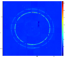
Although few algorithms of automatic quad alignment were tried, we did not find good generic way for automated quad tuning. Currently, the quad tuning parameters in marg_gap_shift and offset_corr are adjusted manually for runs with specific images.
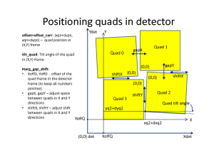
Detector geometry model
In calibration parameters all coordinates are defined in terms of pixel size 109.92um. In this units the reserved square space for each quadrant is 850x850. The margins, shifts and gaps in marg_gap_shift are defined for these quads. The offset and offset_corr are defined for low-left angle of the rotated by n*90 degree quad. Size of entire CSPad image does not matter for this alignment.
Alignment parameters
Location of alignment parameters and file naming conventions
The official space for CSPad alignment parameters is
/reg/d/psdm/<INSTRUMENT>/<experiment>/calib/CsPad::Calib<VERSION>/<CSPad-name>/<type>/<run-range>.data
For example:
/reg/d/psdm/CXI/cxi80410/calib/CsPad::CalibV1/CxiDs1.0:Cspad.0/geometry/1142-end.data
The file name consists of the run range followed by the .data extension, for example, 0-end.data, 11-end.data, 47-52.data, etc.
Description of types
Recommended calibration type
In 2014 new universal detector geometry software is implemented and documented in the Detector Geometry page. In this approach detector geometry calibration information is located in a single file of type
geometry- contains hierarchical description of all detector components; for example for CSPAD, sensors' location and rotation in the quads, quads - in the detector, detector - in the setup, etc.
Currently all psana modules which deals with image and pixel coordinates can work with calibration type geometry.
Deprecated calibration types
All CSPAD geometry alignment parameters are split for 9 types:
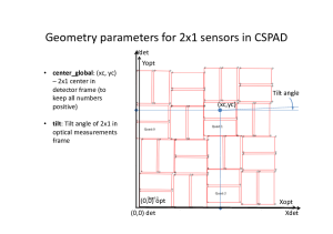
center- x, y, z center position of each 2x1 for all quadrants. Obtained from optical measurement.center_corr- additional manual correction to the center parameter. Can be applied if the optical measurement has (non-)obvious problems.marg_gap_shift- margins, gaps, and shifts between quads, as explained below. Obtained from image-based tuning.offset- x, y, z coordinates for 4 quads. Fairly-reasonable assigned before tuning of theoffset_corrandmarg_gap_shiftparameters.offset_corr- additional correction to the offset. Comes from image-based tuning.quad_rotation- 4 quad rotation in n*90 degree. Comes from basic geometry.quad_tilt- 4 quad tilt in fractional degree. Has never been used. In latest optical measurement is accounted through the global 2x1 coordinate measurement in the detector.rotation- 8 2x1-rotation angle for 4 quads in n*90 degree. Comes from basic geometry.tilt- 8 2x1-tilt angle for 4 quads in fractional degree. Comes from optical measurement.center_global- x, y, z center position of all 2x1 in the detector. Obtained from optical measurement for XPP-type detectors, and can be evaluated from other parameters or image-based tuning for CXI-type detectors.
The same plots in PDF: CSPAD-geometry-parameters.pdf
CSPAD position parameters w.r.t. IP:
beam_vector- (description given by TJ Lane) a R^3 vector pointing from the interaction site to the location ofbeam_intersect(below), along the direction the beam travels. The magnitude of this vector is the distance between the interaction site and the rough plane of the detector.beam_intersect- (description given by TJ Lane) a R^3 vector pointing from the origin (of CSPAD?) to thebeam_vector, and intersecting the beam in an orthogonal manner. This can intuitively be though of as the "center" of the detector – and will be that center in the case that the detector is completely contained in a plane normal to the beam, and the origin is in that plane.
File format for calibration types
geometry
See for details Detector Geometry.
center
Tail of the path: center/<run-range>.data
Parameters: x,y,z coordinates of 8 2x1 centers in 4 quads in pixels:
x0q0 x1q0 x2q0 x3q0 x4q0 x5q0 x6q0 x7q0
x0q1 x1q1 x2q1 x3q1 x4q1 x5q1 x6q1 x7q1
x0q2 x1q2 x2q2 x3q2 x4q2 x5q2 x6q2 x7q2
x0q3 x1q3 x2q3 x3q3 x4q3 x5q3 x6q3 x7q3

y0q0 y1q0 y2q0 y3q0 y4q0 y5q0 y6q0 y7q0
y0q1 y1q1 y2q1 y3q1 y4q1 y5q1 y6q1 y7q1
y0q2 y1q2 y2q2 y3q2 y4q2 y5q2 y6q2 y7q2
y0q3 y1q3 y2q3 y3q3 y4q3 y5q3 y6q3 y7q3

z0q0 z1q0 z2q0 z3q0 z4q0 z5q0 z6q0 z7q0
z0q1 z1q1 z2q1 z3q1 z4q1 z5q1 z6q1 z7q1
z0q2 z1q2 z2q2 z3q2 z4q2 z5q2 z6q2 z7q2
z0q3 z1q3 z2q3 z3q3 z4q3 z5q3 z6q3 z7q3
Typical values:
199.14   198.05   310.67    98.22   629.71   629.68   711.87   499.32
198.52   198.08   311.50    98.69   627.27   627.27   712.35   499.77
198.32   198.04   310.53    97.43   626.68   628.45   710.86   498.01
198.26   198.04   308.70    96.42   627.66   628.04   711.12   498.25

308.25    95.11   625.60   625.70   515.02   727.37   198.53   199.30
307.18    95.08   622.98   623.51   514.99   727.35   199.27   198.94
307.68    95.09   623.95   625.29   512.32   724.63   198.04   200.35
307.39    95.12   627.57   626.65   518.03   730.95   200.02   199.70

  0.31     0.12     0.05     0.12     0.28     0.24     0.40     0.27
  0.45     0.36     0.62     0.33     1.02     0.92     1.30     1.07
  0.23     0.22     0.11     0.15     0.24     0.20     0.60     0.42
  0.25     0.21     0.12     0.10     0.35     0.28     0.66     0.40
center_corr
Tail of the path: center_corr/<run-range>.data
Parameters: x,y,z coordinate corrections of 8 2x1 centers in 4 quads in pixels:
dx0q0 dx1q0 dx2q0 dx3q0 dx4q0 dx5q0 dx6q0 dx7q0
dx0q1 dx1q1 dx2q1 dx3q1 dx4q1 dx5q1 dx6q1 dx7q1
dx0q2 dx1q2 dx2q2 dx3q2 dx4q2 dx5q2 dx6q2 dx7q2
dx0q3 dx1q3 dx2q3 dx3q3 dx4q3 dx5q3 dx6q3 dx7q3

dy0q0 dy1q0 dy2q0 dy3q0 dy4q0 dy5q0 dy6q0 dy7q0
dy0q1 dy1q1 dy2q1 dy3q1 dy4q1 dy5q1 dy6q1 dy7q1
dy0q2 dy1q2 dy2q2 dy3q2 dy4q2 dy5q2 dy6q2 dy7q2
dy0q3 dy1q3 dy2q3 dy3q3 dy4q3 dy5q3 dy6q3 dy7q3

dz0q0 dz1q0 dz2q0 dz3q0 dz4q0 dz5q0 dz6q0 dz7q0
dz0q1 dz1q1 dz2q1 dz3q1 dz4q1 dz5q1 dz6q1 dz7q1
dz0q2 dz1q2 dz2q2 dz3q2 dz4q2 dz5q2 dz6q2 dz7q2
dz0q3 dz1q3 dz2q3 dz3q3 dz4q3 dz5q3 dz6q3 dz7q3
Typical values:
  0    0    0    1    1    0    1    0
  0    0    0    0    0    0   -1    0
  0    0    0    0    0    0    0    0
  0    0    0   -1    0    0    0    1

  0    0    0    0   -1    0   -1    0
  0    0    0    0    0    1    0    0
  0    0    0    0    0    0   -1   -2
  0    0    0    0    0    0    0    0

  0    0    0    0    0    0    0    0
  0    0    0    0    0    0    0    0
  0    0    0    0    0    0    0    0
  0    0    0    0    0    0    0    0
offset
Tail of the path: offset/<run-range>.data
Parameters: x,y,z coordinates of 4 quad "origins" in CSPad pixel matrix:
xq0 xq1 xq2 xq3
yq0 yq1 yq2 yq3
zq0 zq1 zq2 zq3
Typical values:
  0    0  820  820
  0  820  820    0
  0    0    0    0
Due to historical reason offset and offset_corr parameters are defined in rotated frame... (this is a mess...) :
X<--+--------+--------+
    |        |        |
    | Quad 3 | Quad 0 |
    |        |        |
    +--------+--------+
    |        |        |
    | Quad 2 | Quad 1 |
    |        |        |
    +--------+--------+
                      |
                    Y V
offset_corr
Tail of the path: offset_corr/<run-range>.data
Parameters: x,y,z coordinate corrections of 4 quad "origins" in CSPad pixel matrix:
dxq0 dxq1 dxq2 dxq3
dyq0 dyq1 dyq2 dyq3
dzq0 dzq1 dzq2 dzq3
Typical values:
  0   0    5   2
  0   5    4   4
  0   0    0   0
marg_gap_shift
Tail of the path: marg_gap_shift/<run-range>.data
Parameters:
        offset of 2x1s in quad (for tilt)
       /     offset of quads in entire image (for tilt)
      /     /     gaps
     /     /     /    shifts
    /     /     /    /
   XOffQ XOffD gapX shiftX
   YOffQ YOffD gapY shiftY
   ZOffQ ZOffD gapZ shiftZ
Typical values:
   15 40 0 32
   15 40 0 32
    0  0 0  0
quad_rotation
Tail of the path: quad_rotation/<run-range>.data
Parameters: rotation angle of 4 quads in CSPad in n*90 degree:
Aq0 Aq1 Aq2 Aq3
Typical values:
180 90 0 270
quad_tilt
Tail of the path: quad_tilt/<run-range>.data
Parameters: rotation angle correction (tilt) of 4 quads in CSPad in degree:
dAq0 dAq1 dAq2 dAq3
Typical values:
0 0 0 0
rotation
Tail of the path: rotation/<run-range>.data
Parameters: rotation angle of 8 2x1 in 4 quads in n*90 degree:
A0q0 A1q0 A2q0 A3q0 A4q0 A5q0 A6q0 A7q0
A0q1 A1q1 A2q1 A3q1 A4q1 A5q1 A6q1 A7q1
A0q2 A1q2 A2q2 A3q2 A4q2 A5q2 A6q2 A7q2
A0q3 A1q3 A2q3 A3q3 A4q3 A5q3 A6q3 A7q3
Typical values:
  0    0  270  270  180  180  270  270
  0    0  270  270  180  180  270  270
  0    0  270  270  180  180  270  270
  0    0  270  270  180  180  270  270
tilt
Tail of the path: tilt/<run-range>.data
Parameters: rotation angle correction (tilt) of 8 2x1 in 4 quads in degree:
dA0q0 dA1q0 dA2q0 dA3q0 dA4q0 dA5q0 dA6q0 dA7q0
dA0q1 dA1q1 dA2q1 dA3q1 dA4q1 dA5q1 dA6q1 dA7q1
dA0q2 dA1q2 dA2q2 dA3q2 dA4q2 dA5q2 dA6q2 dA7q2
dA0q3 dA1q3 dA2q3 dA3q3 dA4q3 dA5q3 dA6q3 dA7q3
Typical values:
-0.33819   0.00132   0.31452  -0.03487   0.14738   0.07896  -0.21778  -0.10396
-0.27238  -0.00526   0.02545   0.03066  -0.03619   0.02434   0.08027   0.15067
-0.04803  -0.00592   0.11318  -0.07896  -0.36125  -0.31846  -0.16527   0.09200
 0.12436   0.00263   0.44809   0.25794  -0.18029  -0.00117   0.32701   0.32439
center_global
Tail of the path: center_global/<run-range>.data
Parameters: x,y,z coordinates of all 2x1 centers in the detector in units of pixel size (109.92 um).
As usually, the matrix-style of the coordinate system is used:
+--------+--------+-->y
|        |        |
| Quad 3 | Quad 0 |
|        |        |
+--------+--------+
|        |        |
| Quad 2 | Quad 1 |
|        |        |
+--------+--------+
|
V X
x0q0 x1q0 x2q0 x3q0 x4q0 x5q0 x6q0 x7q0
x0q1 x1q1 x2q1 x3q1 x4q1 x5q1 x6q1 x7q1
x0q2 x1q2 x2q2 x3q2 x4q2 x5q2 x6q2 x7q2
x0q3 x1q3 x2q3 x3q3 x4q3 x5q3 x6q3 x7q3

y0q0 y1q0 y2q0 y3q0 y4q0 y5q0 y6q0 y7q0
y0q1 y1q1 y2q1 y3q1 y4q1 y5q1 y6q1 y7q1
y0q2 y1q2 y2q2 y3q2 y4q2 y5q2 y6q2 y7q2
y0q3 y1q3 y2q3 y3q3 y4q3 y5q3 y6q3 y7q3

z0q0 z1q0 z2q0 z3q0 z4q0 z5q0 z6q0 z7q0
z0q1 z1q1 z2q1 z3q1 z4q1 z5q1 z6q1 z7q1
z0q2 z1q2 z2q2 z3q2 z4q2 z5q2 z6q2 z7q2
z0q3 z1q3 z2q3 z3q3 z4q3 z5q3 z6q3 z7q3
Typical values:
    477.78    690.20    159.77    160.06    277.17     64.77    591.30    591.01
    990.78    989.30   1105.38    891.19   1421.65   1423.66   1502.28   1289.93
   1143.85    932.00   1461.86   1463.74   1349.75   1562.62   1032.39   1033.60
    633.06    632.80    518.88    731.75    200.62    198.75    118.50    331.23

   1018.54   1019.42   1134.27    921.94   1451.06   1451.01   1532.55   1319.23
   1173.24    960.71   1490.18   1491.45   1374.97   1587.78   1058.56   1061.14
    658.23    658.54    542.73    755.26    225.91    224.22    146.39    358.27
    507.44    720.59    189.73    190.28    306.25     93.65    620.68    619.85

      1.00      1.04      0.64      1.14      0.05     -0.03     -0.18      0.45
      0.92      1.37      0.26     -0.02      0.62      0.13      1.35      1.25
     -2.10     -1.76     -3.00     -2.29     -3.85     -4.20     -3.63     -2.94
      1.83      1.57      2.23      2.31      1.91      2.07      1.41      0.54
beam_vector
Tail of the path: beam_vector/<run-range>.data
Parameters: 3 components of the vector:
bv_x bv_y bv_z
Typical values:
0 0 0
beam_intersect
Tail of the path: beam_intersect/<run-range>.data
Parameters: 3 components of the vector:
bi_x bi_y bi_z
Typical values:
0 0 0
Pixel coordinate reconstruction
The list of CSPad geometry alignment parameters is over-defined; different parameters can be used to get the same final effect on pixel coordinate. It is done intentionally in order to keep flexibility in the alignment stage.
Algorithm description will be added soon.
Xoffset_qi = XOffQ + xqi + dxqi + [-gapX+shiftX, -gapX-shiftX, +gapX-shiftX, +gapX+shiftX]
Yoffset_qi = YOffQ + yqi + dyqi + [-gapY-shiftY, +gapY-shiftY, +gapY+shiftY, -gapY+shiftY]
...
Software supporting CSPAD geometry
Recommended software to access pixel geometry and produce image is described in Detector Geometry.
Deprecated packages
There is a couple of packages which reconstruct CSPAD pixel coordinates and images developed in C++ and python code;
- C++-based package: Psana Module Catalog - Old#Package CSPadPixCoords.
- Description of C++ package supporting calibration types: CSPAD Geometry Software (depricated).
- Python-based package:
Other useful documents:
- Note about organization of the calibration database: CsPad calibration in translator.
References
- Detector Geometry - confluence page
- CSPAD in DAQ - schematic description of CSPAD geometry available in DAQ.
- CSPAD quad metrology - slides for CXI type CSPAD quads
- CSPad pixel layout in quads - pdf file with numeration of ASICs in the CSPAD quads
Overview
Content Tools