Optical measurement
Run 5 CSPad2-DSD metrology files from Chris Kenney:
2012-01-10-CSPAD2-Configuration.pptx
2012-01-10-Run5-DSD-Metrology.xlsx
2012-01-10-Run5-DSD-Metrology.txt
2012-01-12-Run5-DSD-Metrology-corrected.xlsx
2012-01-12-Run5-DSD-Metrology-corrected.txt
Procedure and table of results
We calculate
S1 - 1st short side of 2x1
S2 - 2nd short side of 2x1
L1 - 1st long side of 2x1
L2 - 2nd long side of 2x1
dS and dL are the deviations of the 1st and 2nd corner along the short and long sides, respectively. The sign of all dS are chosen in order to provide correct sign for the tilt angle (the same direction for all 2x1 sensors).
Everything, excluding <dS/L> and angle(deg), are in micrometers.
pair:        S1      S2     dS1     dS2        L1      L2     dL1     dL2    <dS/L>  angle(deg)

Quad  0
pair: 0   20905   20905     -19     -19     43537   43538      12      13   -0.00044   -0.02500
pair: 1   20906   20900       5      -1     43537   43533       4       0    0.00006    0.00329
pair: 2   20908   20904    -131    -127     43538   43533     -57     -62   -0.00296   -0.16977
pair: 3   20901   20903    -101    -103     43539   43537     -55     -57   -0.00234   -0.13423
pair: 4   20976   20975    -247    -248     43696   43702     113     119   -0.00566   -0.32451
pair: 5   20975   20973    -194    -196     43699   43705      90      96   -0.00446   -0.25566
pair: 6   20904   20901      19      22     43538   43537      14      13    0.00047    0.02698
pair: 7   20909   20910     243     242     43533   43535     117     119    0.00557    0.31916

Quad  1
pair: 0   20900   20908     -22     -14     43536   43538       9      11   -0.00041   -0.02369
pair: 1   20904   20897       7       0     43539   43534      -2      -7    0.00008    0.00461
pair: 2   20987   20979     180     188     43703   43701      89      87    0.00421    0.24123
pair: 3   20977   20975      50      52     43707   43704      31      28    0.00117    0.06686
pair: 4   21383   21371    -167    -179     43904   43915      78      89   -0.00394   -0.22574
pair: 5   21376   21376    -202    -202     43907   43912      95     100   -0.00460   -0.26358
pair: 6   20894   20906    -121    -133     43540   43540     -57     -57   -0.00292   -0.16712
pair: 7   20909   20896     119     132     43545   43543      61      59    0.00288    0.16513

Quad  2
pair: 0   20903   20905     -25     -23     43536   43534      13      11   -0.00055   -0.03159
pair: 1   20905   20903      12      10     43541   43541      -4      -4    0.00025    0.01447
pair: 2   20905   20897       0       8     43537   43543       1       7    0.00009    0.00526
pair: 3   20905   20900     250     255     43543   43540     118     115    0.00580    0.33226
pair: 4   21380   21373    -133    -140     43911   43917      66      72   -0.00311   -0.17809
pair: 5   21381   21387      81      87     43906   43904     -41     -43    0.00191    0.10962
pair: 6   20905   20901    -205    -201     43545   43539     -89     -95   -0.00466   -0.26712
pair: 7   20904   20924    -136    -156     43530   43542     -74     -62   -0.00335   -0.19214

Quad  3
pair: 0   20903   20906    -100     -97     43533   43541      42      50   -0.00226   -0.12963
pair: 1   20900   20900       4       4     43537   43536      -3      -4    0.00009    0.00526
pair: 2   20902   20904    -181    -183     43541   43536     -81     -86   -0.00418   -0.23951
pair: 3   20909   20903    -175    -169     43539   43542     -80     -77   -0.00395   -0.22634
pair: 4   21379   21380     176     177     43906   43917     -91     -80    0.00402    0.23030
pair: 5   21374   21371      65      62     43916   43910     -29     -35    0.00145    0.08285
pair: 6   20904   20906      40      38     43538   43537      22      21    0.00090    0.05132
pair: 7   20902   20895      43      50     43545   43535      30      20    0.00107    0.06119
- All ds1, dl1 are well consistent (within +/-10um) with ds1, dl1, respectively
- Angles of 2x1 are in the range from -0.39 to +0.33 degree.
Configuration parameters
Configuration parameters are shown in number of pixels.
For 2x1 pairs in each quad
Coordinates of the 2x1 centers
- Use the same orientation as in optical measurement, center is calculated as an average of 4 corner coordinates
- All coordinates in pixels
center/0-end.data In pixels:
X(pixel):
 198.46,  198.05,  311.84,   99.32,  628.17,  629.59,  711.73,  499.58,
 198.24,  198.03,  311.37,   98.35,  625.63,  626.78,  711.25,  498.41,
 198.16,  198.04,  309.53,   96.76,  626.36,  626.53,  711.73,  499.20,
 198.36,  198.02,  309.53,   97.25,  627.67,  627.51,  711.80,  499.15,
Y(pixel):
 307.49,   95.11,  626.06,  627.17,  513.15,  725.70,  198.75,  198.39,
 307.48,   95.10,  625.67,  625.63,  510.49,  723.25,  196.42,  196.40,
 307.77,   95.14,  625.26,  624.72,  513.51,  725.92,  199.69,  200.90,
 307.76,   95.09,  627.28,  628.36,  512.75,  725.08,  199.95,  199.96,
Z(pixel):
   0.19,    0.22,    0.42,    0.47,    0.25,    0.48,    0.00,    0.17,
   0.42,    0.27,    0.57,    0.65,    0.55,    0.82,    0.32,    0.38,
   0.05,   -0.17,    0.70,    0.50,    0.63,    1.11,    0.20,   -0.06,
  -0.01,    0.00,   -0.12,   -0.15,   -0.08,   -0.09,    0.06,    0.03,
center_corr/0-end.data are all zeros
2x1-pair orientation angle (degree) in quads
rotation/0-end.data
  0    0  270  270  180  180  270  270
  0    0  270  270  180  180  270  270
  0    0  270  270  180  180  270  270
  0    0  270  270  180  180  270  270
Sensor tilt angle (dergee) from optical measurement
tilt/0-end.data for dPhi:
-0.02500   0.00329  -0.16977  -0.13423  -0.32451  -0.25566   0.02698   0.31916
-0.02369   0.00461   0.24123   0.06686  -0.22574  -0.26358  -0.16712   0.16513
-0.03159   0.01447   0.00526   0.33226  -0.17809   0.10962  -0.26712  -0.19214
-0.12963   0.00526  -0.23951  -0.22634   0.23030   0.08285   0.05132   0.06119
Quads' alignment
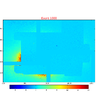
Relative quads' alignment is preliminary done based on cxi80410-r1150, based on DSD image averaged over 1000 events,
where the shadow of mechanical parts can be destinguished. In order to lign-up the boarders of this shadow we apply constants:
marg_gap_shift/0-end.data
15  40   0  24
15  40   0  24
 0   0   0   0
offset_corr/0-end.data
 1 -3  0  1
 1  1 -1 -1
 0  0  0  0
This image still have two degrees of freedom: X- and Y- gap between quads. Currently we set in marg_gap_shift/0-end.data both gaps to zero.
All other parameters have their nominal values:
offset/0-end.data
  0    0  834  834
  0  834  834    0
  0    0    0    0
quad_rotation/0-end.data
180 90 0 270
quad_tilt/0-end.data
0 0 0 0
