LCLS Control System Network Requirements
The LCLS Controls Group has requirements for network access, during the construction of the LCLS, and for the Accelerator itself once operational (the production, or operations network.)
Requirements are organized as Functional, Non-functional, Schedule and Cost. Functional requirements specify what the network must do; non-functional requirements specify qualities that the network must have. Capacity, bandwidth and speed are examples of non-functional requirements. Schedule and Cost requirements are estimates based on current information, and in many cases are yet to be determined.
Functional Requirements
- The SCCS Group at SLAC shall be responsible for the design details and installation of the physical LCLS network as specified in this document. All design and installation details shall be reviewed by the LCLS Controls Group regularly as work proceeds.
- The LCLS network shall support four conceptual subnets, each having distinct requirements. They are referred to as Development, Test, Access Control and Operations.
- Development subnet; the LCLS network shall support a Development subnet for engineering and testing of components to be used in the LCLS accelerator.
- The development subnet shall isolate development activities from other SLAC network activity, while providing full access to other computers on the SLAC network.
- Activity on the LCLS development network shall not interfere with normal activities on the rest of the SLAC network.
- The development subnet shall be accessible to offices in Building 280A, where the LCLS Controls Group currently reside, but also to a few specific Lab areas within SLAC, to be determined as work proceeds.
- The development subnet shall be accessible to desktop computers, laptop computers and single-board computers used by the LCLS Controls Group.
- The LCLS Controls Group shall be able to do day-to-day work on their desktop computers. Specifically, they shall have full access to resources on the SLAC network, and the Internet in general, from specific desktop or laptop computers residing on the development subnet, subject to the network policies in place at SLAC.
- Desktop and laptop computers shall be assigned DHCP or static IP addresses, as per standard SLAC policy.
- The LCLS Controls Group shall have the ability to add any reasonable number of single board computers to the development subnet. These computers shall not be directly accessible from the Internet, nor shall they be able to access anything outside the SLAC network. They are considered to be in an Internet-Free Zone.
- Single board computers on the development subnet shall be assigned static IP addresses, according to standard SLAC policy.
- The development subnet shall contain a development server, which is accessible from all desktop, laptop and single board computers on that development subnet.
- The development server shall be physically accessible to members of the LCLS Controls Group, currently those located in Building 280A.
- Certain specific individuals shall have administrative (root) privilege on the development server, either as a root password or through a "sudo all" capability.
- The development server shall be accessible from Internet through a secure channel. It is not required to be directly accessible from the Internet; it may be accessed indirectly via an intermediate login host.
- The development server shall provide TFTP-based file transfers. TFTP service shall only be made available to IOCs on the development subnet. TFTP service shall not be visible outside of the development subnet.
- The development server shall provide NFS mounted directories as an NFS server, only to IOCs on the development subnet. The NFS mount service need not be visible outside the development subnet.
- The development server shall provide full access to AFS.
- The development server shall provide access to all development tools, including compilers, debuggers, version control and other software deemed necessary by the LCLS Controls Group.
- The development server shall have the ability to provide Web-based access to data or applications. Access to these web-based pages need only be provided to the development subnet.
- The SCCS Group shall specify a backup strategy for the development server.
- Testing subnet; the LCLS network shall support a separate conceptual Testing subnet, on which LCLS Controls engineers can deploy test equipment intended for primary accelerator operations.
-
- The test subnet shall isolate any and all anomalous network activity to that subnet.
- Network test equipment shall reside on this subnet to accommodate testing.
- The Testing subnet is not required to have direct access to the Internet or other SLAC public networks.
- The Testing subnet shall be accessible from, and have access to, the Development network.
- The testing subnet shall provide a set of predefined IP addresses that can be temporarily assigned to network-enabled devices. As a footnote, it is important that an effective policy be implemented to manage the allocation and usage of these temporary addresses.
- Access Control subnet; often referred to as the DMZ subnet, shall provide the only mechanism to access the operations network. The operations network is described under requirement 6 below.
-
- Only those devices in the Access Control subnet shall have access to the Operations network.
- There shall be an SSH Server on the Access Control subnet, which provides the only means by which an individual outside of the control room or accelerator halls can gain login access to the Operations network.
- A subset of SLAC User IDs shall be recognized and enabled by the SSH server, to allow remote login to the Operations network.
- There shall be a Web server located on the Access Control subnet, which shall provide open web-based access to most of the measured data being cached from the Operations network.
- The Web pages from this server shall not be accessible outside of SLAC.
- There shall be an EPICS Gateway server on the Access Control subnet, which will provide software running outside the Operations network with access to specific control and monitor points within the Operations network.
- The EPICS Gateway server shall recognize a subset of SLAC User IDs from specific hosts and provide them remote programmatic access to the Operations network.
- Only software running under an authenticated User ID shall be allowed control system access through the EPICS Gateway server.
- There shall be offline data servers available on the Access Control subnet. The majority of programmatic access to the control system data shall access that data on this server. Specifically, this server shall maintain a regularly updated cache of accelerator controls data.
- Operations network; the LCLS network shall support a separate dedicated network for the commissioning and operation of the LCLS accelerator.
-
- The operations network shall be completely self-contained. Specifically, it shall be able to perform all control system functions and provide all services without a physical connection to any other network.
- The operations network shall provide redundant network switching and connectivity support. For example, certain key pieces of network equipment shall be duplicated such that a failure of one key component will cause a second to come into effect.
- The operations network shall be populated by network devices having IP addresses in the Class A reserved space of 10.X.X.X.
- The SCCS Group shall provide the specific network range in which the IP addresses shall reside. Specifically, the second number in the dotted decimal notation shall be provided by the SCCS Group, effectively specifying a Class B range of addresses. For example, operations network IP addresses may be specified by the SCCS Group to be in the range of 10.10.0.X to 10.10.255.X. This specific address range is our preference.
- The third and fourth set of numbers in the dotted decimal notation shall be assigned by the LCLS Controls Group. The third set of addresses shall refer to subnets having related functionality or geography. For example, 10.10.20.X might refer to the Injection line components, and 10.10.32.X might refer to LTU components.
- The SCCS Group has the option of specifying an address allocation strategy beyond what is described here. For instance, there could be a policy to reserve IP addresses in a certain range for network diagnostic equipment, switches or routers.
- All MAC addresses and IP addresses in use within the operations network shall be recorded and made available to the SCCS Group. Ideally, this will allow easy identification of misbehaving network or computer equipment, or unwanted interaction of network equipment with elements outside the network.
- Physical Layout; the operations network shall be centered in the Main Control Center (MCC) and connect all areas of the LCLS accelerator facility. The diagram in Figure 1 is meant to represent the LCLS accelerator facility, and the labeled, highlighted rectangles indicate where Operations network access is required. Those locations will house the IOCs and related instrumentation. Refer to requirements in Section 6.5.
 Figure 1. LCLS Accelerator Areas and Anticipated IOC Locations. The prefix 'B' refers to existing SLAC Buildings, except those numbered above 900 which represent planned construction with tentative names.
- All operations network nodes shall have the ability to communicate with any other node on the operations network.
- Each IOC shall have its primary ethernet connection on a specific subnet.
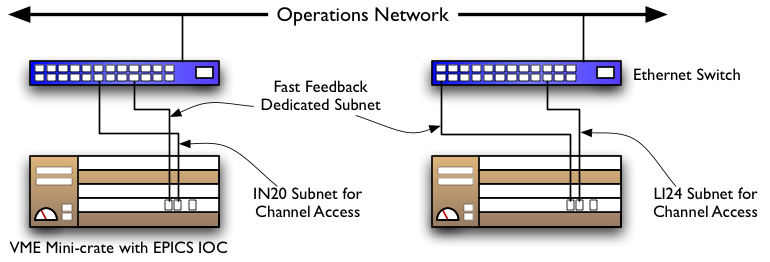
- Certain dual-homed IOCs shall have their secondary ethernet connection on a different subnet from their primary one, but on the same operations network. For example, the following 2 IOCs have primary connections to different subnets, but they are both on a dedicated subnet (VLan) for Fast Feedback. In practice, there could be any number of IOCs having their primary or secondary ethernet ports (but not both) connected to a Fast Feedback dedicated VLan.
 Figure 2. Multi-homed IOCs with a Dedicated Connection
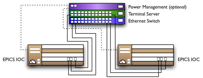
- Each area of the LCLS Accelerator having one or more IOCs shall also have a terminal server. Figure 3 below shows an example of IOC connections. Note that the terminal server and power management units are network devices connected to the ethernet switch, and ultimately to the Operations network. The power management unit is optional, only specific IOC chassis might have one.
 Figure 3. Typical IOC Managed Connections
- Required Network and Serial Ports
- The estimated number of network ports required for each area of the LCLS is summarized in Table 1 below. It is assumed that each ethernet switch is capable of managing 24 network ports, while in practice there may be 48-port switches.Table 1. Network Port Number Estimates, as of February 2006 ||| Area || Location |Network Ports
Injector Area (IN20)| RF Hut in Klystron Gallery, Sector 20, Rack LKG24|96
Injector Vault Stairwell |
48
LI21 |
|
24
LI22 |
|
24
LI23 |
|
24
LI24 |
|
48
LI25 |
|
24
LI26 |
|
24
LI27 |
|
24
LI28 |
|
24
LI29 |
|
24
LI30 |
|
24
Bldg 136 |
|
24
Bldg 106 |
|
24
Bldg 005 (MCC) |
|
72
Bldg 105 |
|
24
Bldg 406 |
|
24
Bldg 911 |
|
24
Bldg 912 |
|
24
Bldg 913 |
|
48
Bldg 921 |
|
48
Front-end Enclosure |
Hutch 1, before Gas Attenuator Area |
24 |
Hutch 2 |
24 |
Hutch 3 |
24
Near-end Hall |
Hutch 2 |
24
X-ray Tunnel |
Between hutches 2 and 3 |
24
Far-end Hall |
Hutch 2 |
24
Total Number of Network Ports |
|
864
Total Number of Ethernet Switches |
|
36 |
-
-
-
- The estimated number of serial ports required for each area of the LCLS is summarized in Table 2 below. Note that a single terminal server is assumed to be capable of 8, 16 or 32 connections depending on a plug-in modules and cable.Table 2. Serial Port Number Estimates as of February 2006 ||| Area || Location |Serial Ports
Injector Area (IN20)| RF Hut in Klystron Gallery, Sector 20, Rack LKG24|24
Injector Vault Stairwell |
16
LI21 |
|
8
LI22 |
|
8
LI23 |
|
8
LI24 |
|
16
LI25 |
|
8
LI26 |
|
8
LI27 |
|
8
LI28 |
|
8
LI29 |
|
8
LI30 |
|
8
Bldg 136 |
|
8
Bldg 106 |
|
8
Bldg 005 (MCC) |
|
16
Bldg 105 |
|
8
Bldg 406 |
|
8
Support Bldg 2.1 |
|
8
Support Bldg 2.2 |
|
8
Support Bldg 2.3 |
|
8
Support Bldg 3.1 |
|
16
Front-end Enclosure |
Gas Attenuator Area |
16 |
Hutch 2 |
16 |
Hutch 3 |
16
Near-end Hall |
Hutch 1 |
16 |
Hutch 3 |
8
X-ray Tunnel |
Hutch 2 |
16 |
Hutch 3 |
16
Far-end Hall |
Hutch 3 |
16
Total Number of Serial Ports |
|
336
Total Number of Terminal Servers |
|
30 |
-
-
- There shall be physical connection point (i.e. RJ45 wall jacks, or "walk-up" taps) located at specific points in the LCLS accelerator equipment areas.
- Only mobile computers and laptops configured by the LCLS Controls Group shall be usable in the LCLS accelerator equipment areas. Other computers will not be recognized nor allowed access to control system functionality on the Operations network, nor will they have access to the Internet or other SLAC services through the Operations network.
- Many locations in the LCLS accelerator equipment areas shall have "walk-up" taps. This includes the injection vault, klystron gallery, Linac tunnel, BSY, LTU and undulator areas, the XTOD areas and the X-ray beamlines. Their numbers are yet to be determined, but they will be part of the port allocation described above for each of those areas.
- Secure and restricted wireless access shall be provided.
- Wireless access shall be available throughout the LCLS accelerator, including the injection vault, klystron gallery, Linac tunnel, BSY, LTU and undulator areas, the XTOD areas and the X-ray beamlines.
- Wireless transceivers shall not be permanently mounted in the accelerator areas. There shall be a small pre-determined number of portable pre-configured transceivers used for commissioning and maintenance purposes.
- Wireless access shall only be available to people having SLAC accounts, who also have LCLS Control System accounts. See Requirement 8.1 below.
- Access to the operations network shall be restricted to a well-known set of users.
- Certain individuals shall be able to login directly to control consoles. These users shall have a standard SLAC computer account, and their LCLS Controls account shall have a user ID consistent with their ID on the SLAC network.
- Certain types of users shall be able to login directly to control consoles in the control room. For instance, there shall be provision for general operator login in the control room, with potentially limited abilities.
- Other users may retrieve data and interact with certain control system software through an EPICS Gateway service, which acts as a proxy. Gateway servers reside on the access control subnet, as stated in requirement 5.4 above.
- The operations network shall be completely isolated, without access from any other SLAC subnet except for the Access Control subnet. Refer to requirement 5, above and a short-term requirement described in requirement 8 below.
- No access to the operations network shall be granted to any device other than one residing on the Access Control subnet.
- Certain SLAC services shall be made available to the operations network. This includes cable, drawing, support and technical databases, which shall be accessible from any operator computer in the Operations network.
- Certain hardware and software resources at SLAC shall be made accessible from the operations network as required. This includes access to file sharing services such as AFS or NFS, or software tools that might be requested on a temporary basis.
- Printing shall be possible from the operations network, and forwarding to printers outside of the operations network shall be possible.
- Several computers shall reside in the operations network for use as file or compute servers.
- No server shall have network connections to any network outside of the operations network.
- At least one server shall provide a copy of the development environment with a complete set of development tools, which will occasionally but regularly be copied from the permanent tool location. These shall be used only during unusual or emergency conditions, when access to the standard SLAC development tools is not available.
- Subnet Requirements
- There shall be a set of virtual networks (VLans) available on the operations network, to provide an organized structure to the network, and to isolate specific functions of the accelerator which have bandwidth or timing requirements. There will be several distinct VLans available, to be identified as design work proceeds.
- The Fast Feedback subsystem shall have a separate VLan, and will be populated by several IOCs with Beam Diagnostic data, and others with Magnet Control capabilities.
- The Low-level RF (LLRF) subsystem shall have a separate VLan, populated by several IOCs with RF phase, amplitude and other related readout and control capabilities.
- The Beam Profile Camera subsystem for OTR and YAG monitors shall have a separate VLan for camera image data. This is considered a tentative requirement pending further beam diagnostic design.
- The Machine Protection System (MPS) shall occupy a separate VLan.
- All other subsystems shall have the ability to belong to a separate VLan dedicated to that subsystem. Details are forthcoming pending design decisions.
- Temporary SLC-aware IOC Connection
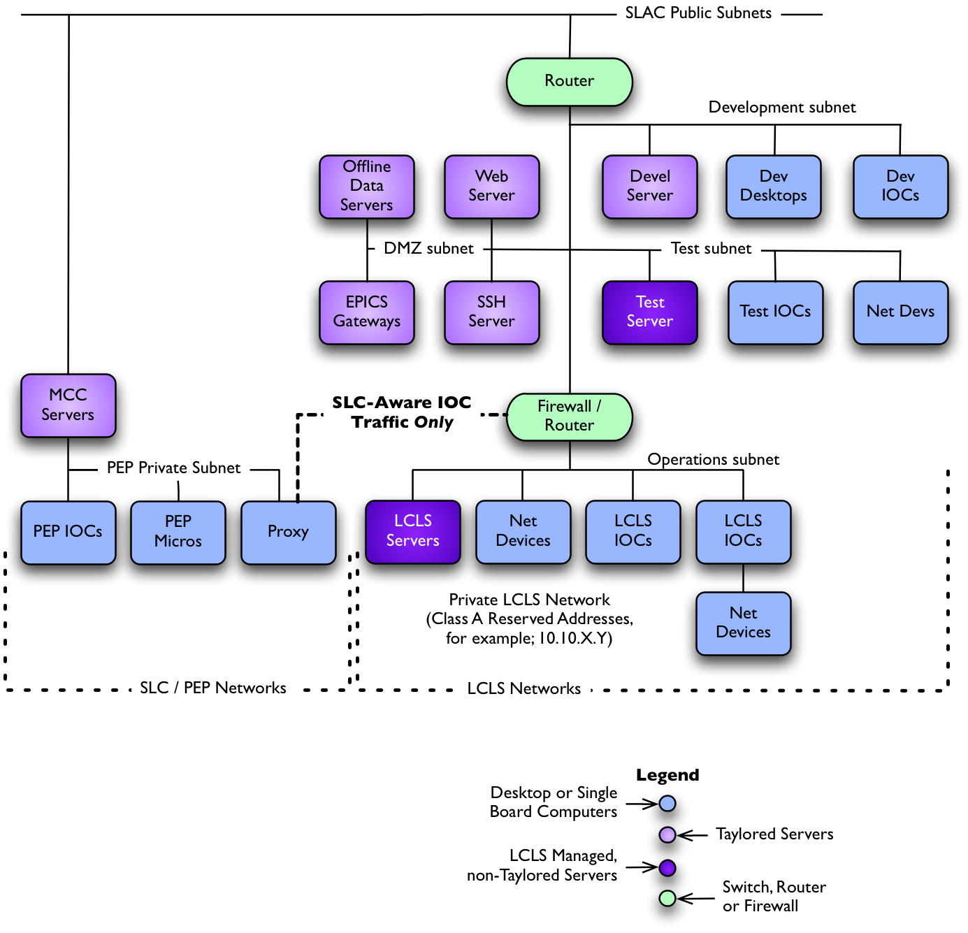
- Short-term access to the SLC/Linac Accelerator Control Network shall be provided, to allow the existing MCC Control System to control SLC-aware IOCs.
- Access to the LCLS operations network shall be provided to a specific SLC Proxy server. This SLC Proxy server shall have access only to a specific set of IOCs on the LCLS operations subnet.
- The VMS computer currently used for accelerator controls shall have secure access to a file server located in the LCLS operations network.
Non-functional Requirements
- Development subnet; all network devices on the development subnet shall have the ability to communicate at speeds up to 100 Mbps.
- Test subnet; all network devices on the test subnet shall have the ability to communicate at speeds up to 100 Mbps.
- Access Control subnet; all network devices on the access control subnet shall have the ability to communicate at speeds up to 1000 Mbps.
- Connections to other subnets in the LCLS network, or in the larger SLAC network shall have the ability to communicate at 100 Mbps.
- Connections to the Operations network from the Access Control subnet shall have the ability to communicate at speeds up to 1000 Mbps.
- Operations network; all network devices on the operations network shall have the ability to communicate at speeds up to 1000 Mbps.
Schedule Requirements
- The Development subnet shall be implemented in several stages to accommodate LCLS Controls Group development work.
- The Development server shall be physically installed by November 1, 2005.
- The Development server shall be setup and configured by December 1, 2005.
- Developers shall be able to configure IOCs, build software and do basic IOC tests on the development subnet by December 1, 2005.
- The Test subnet shall be implemented as needs arise, but not before December 31, 2005.
- The Operations network shall be implemented according to a detailed schedule (see separate document) with specific milestones.
- Network access to the injector area building at sector 20 shall be available by May 15, 2006.
- Network access to the klystron galleries for each sector from 21 through 30 shall be available by December 2007.
- Network access to the Linac BSY and LTU areas shall be available by April 2008.
- Network access to the Undulator hall, beam dump and Front-end enclosure areas shall be available by June 2008.
- Network access to the Front-end enclosure of the XTOD area shall be available by June 2008.
- Network access to the Near Hall of the XTOD area shall be available by June 2008.
- Network access to the X-ray transport lines of the XTOD area shall be available by September 2008.
- Network access to the Far Hall of the XTOD area shall be available by November 2008.
Cost Requirements
- The total cost of the development subnet equipment shall be the responsibility of the SCCS group and the LCLS Controls Group.
- The cost of cables, switches and other network related hardware for the development subnet shall be the responsibility of the SCCS Group, according to current SLAC computing policy.
- The cost of servers, desktop computers, laptops and single board computers for the development subnet shall be the responsibility of the LCLS Controls Group.
- The total cost of the test subnet shall be the responsibility of the LCLS Controls Group.
- The total cost of the Access Control subnet equipment shall be the combined responsibility of the SCCS group and the LCLS Controls Group.
- The cost of cables and ethernet switches for the access control subnet shall be the responsibility of the SCCS Group, according to current SLAC computing policy.
- The cost of other network equipment such as terminal servers, remote power management units, as well as computers such as servers, desktop computers, laptops and single board computers for the access control subnet shall be the responsibility of the LCLS Controls Group.
- The total cost of the Operations network equipment shall be the responsibility of the LCLS Controls Group.
Suggestions for Implementation
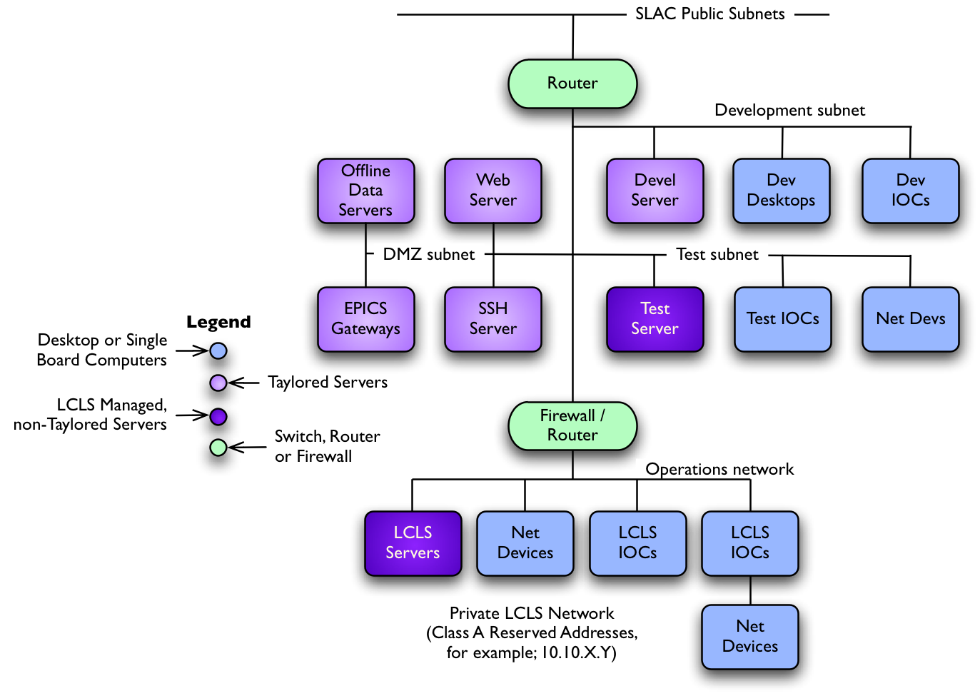
The diagram in Figure 4 shows a conceptual layout of the required network. The four networks described above are shown; the operations network, and the development, test and access control (DMZ) subnets.  Figure 4. The LCLS Conceptual Network
Although the development, test and access control subnets are conceptually on the same level, they may in practice be on completely different subnets, separated by layers of network equipment.
The diagram in Figure 5 shows a few of the components from the existing SLAC/PEP control system, and specifically the linkage implied from requirement 8.1 above.  Figure 5. The SLC/PEP Connection From The LCLS


