Requirements (From Alan Fisher):
An amplifier/attenuator on each diagnostic signal. This was motivated by Jim Welch’s calibration procedure, which would benefit from seeing the loss location for hits on each fiber. The wire scanners need amplification, since only a small charge is kicked out by the wire. Jim needs attenuation, since he splats the entire bunch onto the wall of the beampipe. A fiber PLIC may be best with no gain or attenuation. The chips to use (two AD603s in cascade) give both gain and attenuation, depending on a control voltage. The gain control is exponential—a linear conversion from control voltage to dB of gain.
cascadedAD603amps.pdf
I am attaching a calculation (as a Matlab live script and as a PDF) of the gain in dB vs. DAC voltage, to aid in creating the user’s gain control. It includes a formula which attempts to take the rounded end points into account as each of the two cascade chips runs through its gain range in sequence (the first from DAC voltages of -0.5 to +0.5 and the second from +0.5 to +1.5). As we discussed, the user should have a slider control marked in dB, along with an input box that allows typing the desired gain instead, for convenience; the slider and the input box both indicate the gain. The selected gain should be converted into the corresponding DAC voltage, from -0.65 to +1.65 V.
The chassis bypasses the amplifier if the DAC voltage is less than -1 V. There should be a bypass on/off switch that sets the DAC to something about -1.2 V (to be far from the transition). When bypassed, the path attenuates by -5.6 dB (almost a factor of 2 in voltage). When the bypass is turned off, the DAC can go to 0 V, since that gives almost the same gain, -5.2 dB. The user won’t see a big jump and can tweak from there.
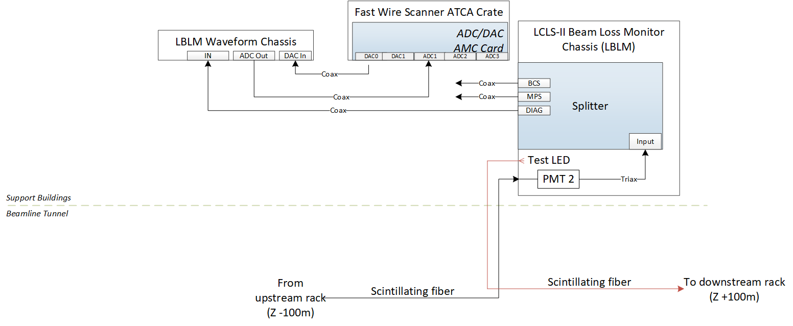
Block Diagram:
Testing:
- Set registers to manipulate DAC out between -0.65 to 1.65V - use treeGUI
- Expose registers to manipulate from EPICS
- Add dB vs volatage conversion into EPICS
- Add Bypass PV which sets voltage to -1.2V. User should not be able to write to Voltage PV
- When bypass is unselected, voltage should be set to 0V
- pyDM screen
Test1.