Introduction

The 2-slot crate located at Andrew's bench gives probing access and measurements otherwise inaccessible inside the ATCA crate. Common uses of the 2-slot crate include checking voltages, attenuator bits, and amplifier/switch debugging.
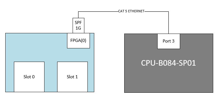
Connection Diagram
- FPGA Port 0 ↔ Port 3 on CPU-B084-SP01


Using the 2-slot debug crate
Start the software:
- log in to lcls-dev3
ssh laci@cpu-b084-sp01ping 10.0.0.101 (Check connection)- In bash:
Open the UI
- open a new lcls-dev3 window
cd /afs/slac/g/lcls/package/cpsw/cpswTreeGUI/current/./env.slac.shpython3 cpswTreeGUI.py --ipAddress=10.0.0.101 --rssiBridge=cpu-b084-sp01 --disableStreams ~disco/scripts/B084_TestStand/stripline_yaml/AmcCarrierBpmStriplineDDV1_project.yaml/000TopLevel.yaml NetIODev&
- Or
~disco/scripts/bash/ControlGUI.sh
- Under the mmio tab "right mouse" click "load file" <default.yaml>
GUI Guide (once connection is made the GUI should not show ??? in the value fields):
Turn on Calibration:
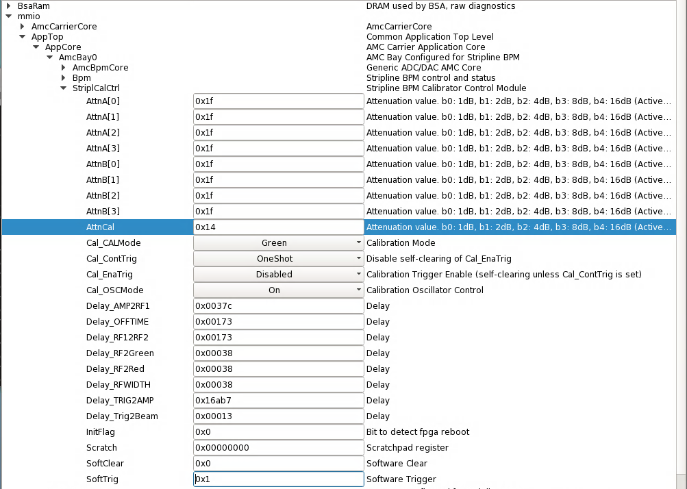
Pulse generation steps:
- mmio
- AppTop
- AppCore
- AmcBpmCore
- StripCalCtrl
- AttnCal - set to 0x14
- Cal_CALMode - Red or Green
- Cal_ContTrig - OneShot
- Cal_EnaTrig - Enabled (will reset after each shot)
- Cal_OSCMode (On)
- SoftTrig - (input 0x1 and enter will generate only 1 cal tone for 100us, and need to reset after each shot)
- !! - By hitting enter, a large power pulse will be generated by the amplifier. Make sure termination and attenuation are in place before doing this.
Amplifier Check:
- Turn resistor R30 side-ways:
- Connect SMA-Pin hole connector to oscilloscope, add series termination pad of minimum 20dB to scope
- Set probe/OSC to 50 ohm termination
- Connect J105 to probe
- Set time base to max. 20us per division
- Set vertical scale to 50mV per division
- Set trigger around 50mV
- Set AttnCal in mmio GUI to 0x14 (20dB attenuation)
- Follow pulse generation steps above to create signal
- Observe signal on the screen. Reference good signal shown below (at J105):

- If RF switches are working, and cables from J102 to J101, J104 to J103 are attached, green and red channels will look like:
-


Set Attenuation:
- mmio
- AppTop
- AppCore
- AmcBpmCore
- StripCalCtrl
- AttnA/B[x] - set value in hex
Attenuation Truth Table:
Hex Value | Binary Value | Pin Voltage Level V5, V4, V3, V2, V1 | Attenuation Value |
|---|
Hex Value | Binary Value | Pin Voltage Level V5, V4, V3, V2, V1 | Attenuation Value |
|---|
| 0x1F | 0b11111 | 00000 | 31dB |
| 0x1E | 0b11110 | 00005 | 30dB |
| 0x1D | 0b11101 | 00050 | 29dB |
| 0x1C | 0b11100 | 00055 | 28dB |
| 0x1B | 0b11011 | 00500 | 27dB |
| 0x1A | 0b11010 | 00505 | 26dB |
| 0x19 | 0b11001 | 00550 | 25dB |
| 0x18 | 0b11000 | 00555 | 24dB |
| 0x17 | 0b10111 | 05000 | 23dB |
| 0x16 | 0b10110 | 05005 | 22dB |
| 0x15 | 0b10101 | 05050 | 21dB |
| 0x14 | 0b10100 | 05055 | 20dB |
| 0x13 | 0b10011 | 05500 | 19dB |
| 0x12 | 0b10010 | 05505 | 18dB |
| 0x11 | 0b10001 | 05550 | 17dB |
| 0x10 | 0b10000 | 05555 | 16dB |
| 0x0F | 0b01111 | 50000 | 15dB |
| 0x0E | 0b01110 | 50005 | 14dB |
0x0D | 0b01101 | 50050 | 13dB |
| 0x0C | 0b01100 | 50055 | 12dB |
| 0x0B | 0b01011 | 50500 | 11dB |
| 0x0A | 0b01010 | 50505 | 10dB |
| 0x09 | 0b01001 | 50550 | 9dB |
| 0x08 | 0b01000 | 50555 | 8dB |
| 0x07 | 0b00111 | 55000 | 7dB |
| 0x06 | 0b00110 | 55005 | 6dB |
| 0x05 | 0b00101 | 55050 | 5dB |
| 0x04 | 0b00100 | 55055 | 4dB |
| 0x03 | 0b00011 | 55500 | 3dB |
| 0x02 | 0b00010 | 55505 | 2dB |
| 0x01 | 0b00001 | 55550 | 1dB |
| 0x00 | 0b00000 | 55555 | 0dB (Reference) |
